Ubuntu: Basic Mail Server Configuration


We will try to install and configure a mail server solution in Ubuntu. We will use postfix as the SMTP server and Dovecot as the IMAP/POP3 server. We will also use Thunderbird as the client agent for testing purpose. Before you could install a mail server, you need to have a running DNS server with an MX record in it for your domain. Refer to this post on how to configure a DNS server.


First, download and install postfix with the command


sudo apt-get install postfix


When the installation is done, you will be asked by several questions, answer them with the following:


  • Internet Site
  • mail1.example.com (change this to what you want your mail server name and domain name to be)
  • administrator (change this to the administrator username)
  • mail.example.com, example.com, localhost.example.com, localhost (you can leave it as default or change this to suit your mail server and domain name)
  • No
  • 127.0.0.0/8 [::ffff:127.0.0.0]/104 [::1]/128 192.168.0.0/24 (you can leave it as default)
  • 0
  • +
  • all

Now, change the mailbox format used to Maildir with the command.


sudo postconf -e 'home_mailbox = Maildir/'
sudo postconf -e 'mailbox_command ='


The Maildir format will place each mail as a file in /home/username/Maildir. Now, verify postfix installation with the command (change mail1.example.com to your mailserver name or any other name just for testing purpose)


telnet localhost 25
ehlo example.com


If you are connected and you get responses, then postfix is running. Before we test sending an email, let's install Dovecot as the IMAP/POP3 server. Get and install Dovecot with the following command


sudo apt-get install dovecot-imapd dovecot-pop3d


Now, some configuration changes needs to be done to /etc/dovecot/dovecot.conf. Open the file using your favourite text editor. First, we will set the protocol that will be used supported by dovecot, search for the following protocols entry and change the value to support which protocol that you prefer.


protocols = pop3 pop3s imap imaps

configure dovecot to use Maildir format, search for the mail_location entry (it is commented by default) and set the value to the following


mail_location = maildir:~/Maildir

To allow login from remote machine, search for the "listen" parameter and set it to


listen = *

For Thunderbird specific configuration, search for the IMAP configuration part "protocol imap {", then search for "imap_client_workarounds" parameter before the closing bracket. Change it to


imap_client_workarounds = tb-extra-mailbox-sep

Then, add the Maildir skeleton directory to /etc/skel to automatically create the Maildirr directory structure for newly created users. Run the following command


sudo maildirmake.dovecot /etc/skel/Maildir
sudo maildirmake.dovecot /etc/skel/Maildir/.Drafts
sudo maildirmake.dovecot /etc/skel/Maildir/.Sent
sudo maildirmake.dovecot /etc/skel/Maildir/.Trash
sudo maildirmake.dovecot /etc/skel/Maildir/.Templates

Now, restart Dovecot and test if it is running. Run the following command


sudo /etc/init.d/dovecot start
telnet localhost pop3
telnet localhost imap2


If Dovecot is running correctly, you should get respond when you're connecting to the POP3 and IMAP server. Next, is to try to connect to the mailserver by using a client agent. We will use Thunderbird, if you haven't installed Thunderbird, get and install it. I believe it is not hard to be found. Before start configuring Thunderbird, let's add a localuser named "joe" at the mailserver for testing purpose with the command


sudo useradd -m -s /bin/bash joe
sudo passwd joe


Now, let's configure Thunderbird so that joe can check his mail on the mailserver. Once you've installed Thunderbird on the client, run it, then click the File > New > Mail Account. A dialog box will appear to configure a new mail account, fill in the your name, email address and password (the value depends on what you've set for joe's password) to match joe's account


Click Continue, Thunderbird will try to resolv the POP3/IMAP server and the SMTP server for the domain. If Thunderbird failed to resolv the mail server, Then click Manual Configuration. On the Server Name, fill in the mail server's hostname or IP address. Choose the port number 110 for POP3 or 143 for IMAP. Choose STARTTLS at the Connection security and Normal Password at the Authentication Method. Then click OK


You will notice that Thunderbird will list your newly created account on the left hand side. Right click on the account name, in this case "joe@example.com", then click Settings. Make sure the selected server for Outgoing Server (SMTP) is correct, if not, you can manually add your SMTP server into Thunderbird. On the left hand side of the dialog, look for the most bottom entry, there will be an Outgoing Server (SMTP) entry. Click Add, Then fill in the server name, which is the SMTP hostname or IP addres. Choose the connection security settings and Authentication Method used by your SMTP server, in this example, choose STARTTLS and No Autentication respectively. Click OK, then go back to the account setting, and select the correct SMTP server at the Outgoing Server (SMTP) entry.


Now, you can add another user to the mail server local user for testing purpose, then try to send email from one to another. You will received the email in Thunderbird. For further enhancement, you will want to add authentication to postfix, therefore disabling spammers to use your SMTP server to send emails, Integrating Dovecot with LDAP for Single Sign-On, installing and configuring spam assasin.


Read more...

Ubuntu: DNS Server


We will configure a DNS server on a Ubuntu machine. This server will act as the master DNS for the local domain in this example, which is example.com. First, get the bind9 and the utility package with the commands


sudo apt-get install bind9
sudo apt-get install dnsutils


Now, add the "zone" (domain) to /etc/bind/named.conf.local. Use your favourite text editor to edit that file. and add the following (you will need the super user privilege to edit the file).


zone "example.com" {
type master;
file "/etc/bind/db.example.com";
};

zone "1.168.192.in-addr.arpa" {
type master;
notify no;
file "/etc/bind/dbreverse.example.com";
};


From the above example, two zones are created. First is example.com zone. This zone will have entry of hosts stored in file /etc/bind/db.example.com, which will need to be created later. The second zone is 1.168.192.in-addr.arpa, the reverse zone which will holds the entry to resolv ip address to hostname. You need to change 1.168.192 with whatever private network address that you need in reverse order. If you use network 192.168.0.0/16, then the zone name must be 168.192.in-addr.arpa. Recognize that all of the db files are referenced with the absolute path, if relative path is given, bind9 will start finding the file from /var/cache/bind, like how it is configured in /etc/bind/named.conf.options.


Now, create the file, db.example.com in /etc/bind. Add the following to the file.


$TTL 604800
@ IN SOA ns.example.com. root.example.com. (
2011010101 ; Serial
604800 ; Refresh
86400 ; Retry
2419200 ; Expire
604800 ) ; Negative Cache TTL
;
@ IN NS ns.example.com.
@ IN MX 10 mail.example.com.

ns IN A 192.168.1.133
mail IN A 192.168.1.140
host1 IN A 192.168.1.1
gateway IN CNAME host1


In this file, the ";" sign mark the start of a comment, and whatever follows will be ignored by the DNS parser. The first line is the TTL value, this value tells how long does other DNS server can cache infomation queried from this server. The next line is the State of Authority record. The @ symbol is a shotcut for the zone name declared in /etc/bind/named.conf.local, IN specify that this DNS resource is the internet class. We will use this value most often. SOA should always be there. The next entry is the hostname of the DNS server that could provide DNS service for the domain. You can specify the FQDN of the nameserver, but remember to always put a dot at the end of the name server. The nxt entry is the email address of someone who is responsible of this zone, remember to always put a dot at the end of the entry if it is a FQDN. the next fields consists of several entries that are enclosed with a set of parenthesis. Those are


  • Serial. This number should always be incremented everytime a change has been made to the file. Most people will use the yyyymmddnn format, with the nn is the sequence number, giving you the feasible value of 00-99 for a day.
  • Refresh Interval. This is the value in seconds after which a slave DNS server will update its zone and reverse zone information from the master
  • Retry. This is the value in which if a slave DNS server failed to contact the master to update its zone and reverse information, should retry to contact the master after the amount of this value has elapsed. This value should be much smaller than the Refresh value.
  • Expiration. This is the amount of time which information in slave DNS server should be considered expired. If a slave DNS server failed to update its zone and reverse information and the amount of time in this entry has elapsed, it will stop responding queries asking information about this domain.
  • Negative Cache TTL. The amount of time that a negative response, such as a nonexistent domain response, will be cached by the DNS server.


The next part of the file is the entry that defines hostname to ip address. As can be seen, there is a nameserver, mail, host and alias entry. The nameserver record, marked with NS specify what is the name of the nameserver in this zone. The mx record, which is the mailserver record looks the same as the NS record except that it uses MX and there is a sequence number, in this case 10, specifying which mailserver will be preffered in the domain. Both of the records point to a hostname, therefore we need to specify the ip address of those hostname and that is done with the A record. The CNAME record specify an alias, in this example gateway is an alias for host1 and therefore, both will resolv to the same address. You can modify the value of this entries based on your requirement.


Next, create the reverse zone file information. Create the /etc/bind/dbreverse.example.com and fill the file with the following.


$TTL 604800
@ IN SOA ns.example.com. root.example.com. (
2011010101 ; Serial
604800 ; Refresh
86400 ; Retry
2419200 ; Expire
604800 ) ; Negative Cache TTL
;
@ IN NS ns.example.com.
133 IN PTR ns.example.com.
140 IN PTR mail.example.com.
1 IN PTR host1.example.com.


Basically, in the reverse zone file you have to create a PTR record for each A record in the zone file. Now restart bind9 with the command


sudo /etc/init.d/bind9 restart


Next, add an entry of your newly configured nameserver in /etc/resolv.conf. add the following line to the beginning of file


nameserver 192.168.1.133


Change 192.168.1.133 to whatever your DNS server ip address is. Then, you can verify your configuration by using the dig command. Try the following command,


dig ns.example.com


If your configuration is working, it should give an output similar to this


; <<>> DiG 9.7.0-P1 <<>> ns.example.com
;; global options: +cmd
;; Got answer:
;; ->>HEADER<<- opcode: QUERY, status: NOERROR, id: 47515
;; flags: qr aa rd ra; QUERY: 1, ANSWER: 1, AUTHORITY: 1, ADDITIONAL: 0

;; QUESTION SECTION:
;ns.example.com. IN A

;; ANSWER SECTION:
ns.example.com. 604800 IN A 192.168.1.133

;; AUTHORITY SECTION:
example.com. 604800 IN NS ns.example.com.

;; Query time: 1 msec
;; SERVER: 127.0.0.1#53(127.0.0.1)
;; WHEN: Sat Oct 2 21:21:32 2010
;; MSG SIZE rcvd: 62


Read more...

Ubuntu: OpenLDAP


We will install OpenLDAP in Ubunt server. Here, I user Ubuntu server 10.04. After that we will use OpenLDAP for authentication. First, download and install OpenLDAP by using apt-get.


sudo apt-get install slapd ldap-utils


Next, load some schemas to LDAP (LDAP schemas give structure/attributes to LDAP classes, the following schemas will be used for adding users later)


sudo ldapadd -Y EXTERNAL -H ldapi:/// -f /etc/ldap/schema/cosine.ldif
sudo ldapadd -Y EXTERNAL -H ldapi:/// -f /etc/ldap/schema/nis.ldif
sudo ldapadd -Y EXTERNAL -H ldapi:/// -f /etc/ldap/schema/inetorgperson.ldif


Then, load the backend configuration to LDAP. Copy the following configuration to a file, name it backend.ldif


# Load dynamic backend modules
dn: cn=module,cn=config
objectClass: olcModuleList
cn: module
olcModulepath: /usr/lib/ldap

olcModuleload: back_hdb


# Database settings
dn: olcDatabase=hdb,cn=config

objectClass: olcDatabaseConfig
objectClass: olcHdbConfig
olcDatabase: {1}hdb
olcSuffix: dc=example,dc=com
olcDbDirectory: /var/lib/ldap
olcRootDN: cn=admin,dc=example,dc=com
olcRootPW: adminpw
olcDbConfig: set_cachesize 0 2097152 0
olcDbConfig: set_lk_max_objects 1500
olcDbConfig: set_lk_max_locks 1500
olcDbConfig: set_lk_max_lockers 1500
olcDbIndex: objectClass eq
olcLastMod: TRUE
olcDbCheckpoint: 512 30
olcAccess: to attrs=userPassword by dn="cn=admin,dc=example,dc=com" write by anonymous auth by self write by * none
olcAccess: to attrs=shadowLastChange by self write by * read
olcAccess: to dn.base="" by * read
olcAccess: to * by dn="cn=admin,dc=example,dc=com" write by * read


Take a look at the olcSuffix, olcRootDN and the olcRootPW entry. The olcSuffix is the domain name, here we use example.com as the domain name. The olcRootDN is the DN that has the administrator privilege like. olcRootPW is the password for the root admin. You may want to change those value to meet your requirement. If everything is fine, load the configuration to LDAP with the command


sudo ldapadd -Y EXTERNAL -H ldapi:/// -f backend.ldif


Next, fill the frontend directory to LDAP. This is where we create our organization tree, the domain, ou, user, group, ect. Copy the following to a file named frontend.ldif


# Create top-level object in domain
dn: dc=example,dc=com
objectClass: top
objectClass: dcObject
objectclass: organization
o: Example Organization
dc: Example
description: LDAP Example


# Admin user.
dn: cn=admin,dc=example,dc=com
objectClass: simpleSecurityObject
objectClass: organizationalRole
cn: admin
description: LDAP administrator
userPassword: secret


dn: ou=people,dc=example,dc=com
objectClass: organizationalUnit
ou: people


dn: ou=groups,dc=example,dc=com
objectClass: organizationalUnit
ou: groups


dn: uid=john,ou=people,dc=example,dc=com
objectClass: inetOrgPerson
objectClass: posixAccount
objectClass: shadowAccount

uid: john
sn: Doe
givenName: John
cn: John Doe
displayName: John Doe
uidNumber: 1000
gidNumber: 10000
userPassword: password
gecos: John Doe
loginShell: /bin/bash
homeDirectory: /home/john
shadowExpire: -1
shadowFlag: 0
shadowWarning: 7
shadowMin: 8
shadowMax: 999999
shadowLastChange: 10877
mail: john.doe@example.com
postalCode: 31000
l: Toulouse
o: Example
mobile: +33 (0)6 xx xx xx xx
homePhone: +33 (0)5 xx xx xx xx
title: System Administrator
postalAddress:
initials: JD


dn: cn=example,ou=groups,dc=example,dc=com
objectClass: posixGroup
cn: example
gidNumber: 10000


In the example above, we create a user with uid: john. under the people oum the uid and the userPassword attributes will be used for authentication later. A group named example is also created under the groups ou and john is a member of that group. Change the value of ou, user information to meet your requirement. What should be taken into consideration here is the uidNumber attribute of the user. This uidNumber should be unique, it should not be the same with other user, even with the local user. You can check if the uidNumber has been used by local user by checking the "/etc/passwd" file. In above example, john's uidNumber is 1000. To check if this uid number has been used by local user, enter the following command


egrep ":1000:" /etc/passwd


If there's any output, then it has been used. If everything has been set, then load the frontend directory to OpenLDAP with the following command


sudo ldapadd -x -D cn=admin,dc=example,dc=com -W -f frontend.ldif


We have finished populating LDAP directory, next we will configure to use LDAP user for authentication


LDAP Authentication


To configure LDAP for authentication, first we need to install the libnss-ldap package.


sudo apt-get install libnss-ldap


After finishing the installation, you wll be asked several questions. Assume that you use the example.com as your domain, for each question enter the following answer


  • ldapi:///example.com
  • dc=example,dc=com
  • 3
  • No
  • No

Then, enable auth-client-config LDAP profile


sudo auth-client-config -t nss -p lac_ldap


Now, enable PAM for LDAP by the command


sudo pam-auth-update


Choose LDAP and any other authentication mechanism if needed. Now, you should be able to login using your OpenLDAP user, in this example, as john. But something still has to be done. If we recall from the user entry in frontend.ldif file, we specify the home directory of john to be "/home/john", but this directory is not exist yet (not if you have created it before). The problem here is that, since we are adding user from LDAP, user's home directory is not automatically created. This is different from adding local user with the "useradd -m " command.


Creating User's Home Directory


Using your favourite text editor, edit the file "/etc/pam.d/common-session". Add the following entry if not exist


session required pam_unix.so
session required pam_mkhomedir.so skel=/etc/skel/
session optional pam_ldap.so
session optional pam_foreground.so


Now, if you logged using your LDAP user for the first time, user's home directory will be created.


Read more...

Ubuntu: Interface IP Addressing


Interface addressing includes how to change the ip address of an interface, the default gateway and also the DNS address. You can do temporary or permanent changes. To temporarily change the ip address of an interface, use the following command


sudo ifconfig eth0 A.B.C.D netmask X.X.X.X


A.B.C.D: the new ip address
X.X.X.X: the netmask of the ip address


The example above will change the ip address and the netmask of the eth0 interface. Change eth0 from the command above to other interface based on your need. Verify the changes by using the command "sudo ifconfig eth0" If you change the ip address of an interface, chances are that you also want to configure the default gateway. To do that, use the command


sudo route add default default gw X.X.X.X eth0


X.X.X.X: the ip address of the default gateway


Verify that configuration by using the command "route". The output should display a route to your default gateway.


Next, to make a permanent changes there is a file that has to be edited. The network configuration is kept in "/etc/network/interfaces", open the file and you will see what is inside the file that would look something like this.


There are two interfaces in the example above, l0 and eth0. Now, from the example above, eth0 has been configured to use dhcp. If you want to edit an interface to use dhcp configuration, follow the configuration


auto eth0
iface eth0 inet dhcp


That are the what should be entried in the "etc/network/interfaces" file. After that, you can use the command "sudo ifup eth0" to refresh and initiate the DHCP process. But, if we want to configure the ip address and default gateway statically, edit at the appropriate interface part and add these lines


auto eth0
iface eth0 inet static
address 192.168.1.10
netmask 255.255.255.0
gateway 192.168.1.1


Change the ip addressing to suit your requirement.


Read more...

Configuring BGP


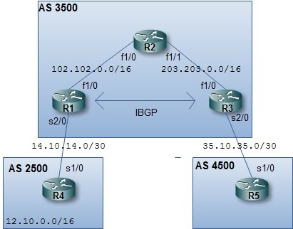
BGP configuration is quite different from other routing protocols configuration. There are two kinds of BGP, which are IBGP and EBGP. EBGP is when BGP is configured between routers in a different Autonomous System (AS), IBGP is when BGP is configure between routers within the same AS. EBGP behaves differently from IBGP. We will see what other differences are as we configure BGP in the following topology.


In BGP we have to specify each of our neighbor manually and the network command work differently as with other routing protocol. We will start by configuring every interface and start BGP in each router.


R1


interface FastEthernet1/0
ip address 102.102.0.1 255.255.0.0
no shutdown
interface Serial2/0
ip address 14.10.14.1 255.255.255.252
no shutdown
interface loopback0
ip address 1.1.1.1 255.255.255.255
router bgp 3500


R2


interface FastEthernet1/0
ip address 102.102.0.2 255.255.0.0
no shutdown
interface FastEthernet1/1
ip address 203.203.0.1 255.255.0.0
no shutdown


R3


interface FastEthernet1/0
ip address 203.203.0.2 255.255.0.0
no shutdown
interface Serial2/0
ip address 35.10.35.1 255.255.255.252
no shutdown
interface loopback0
ip address 3.3.3.3 255.255.255.255
router bgp 3500


R4


interface loopback0
ip address 12.10.0.1 255.255.0.0
no shutdown
interface Serial1/0
ip address 14.10.14.2 255.255.255.252
no shutdown
router bgp 2500


R5


interface Serial1/0
ip address 35.10.35.2 255.255.255.252
no shutdown
router bgp 4500


At this point, you can run the "show processes" or only "show processes | include BGP" (the BGP should be in upper case) command to see that BGP processes is running. You can also use the "show processes cpu | include BGP" to see the cpu usage instead of the memory usage.


Now, all interfaces have been configured and BGP processes are running. We can now make them BGP neighbor. There could be two type of BGP neighbor, IBGP or EBGP neighbor. EBGP neighbor is a neighbor of which AS number is different from the AS number of the configured router. First we will configure EBGP peers between R1-R4 and R3-R5. Neighbor in BGP should be configured manually, here is the configuration (enter the configuration at each BGP )


R1


router bgp 3500
neighbor 14.10.14.2 remote-as 2500


R4


router bgp 2500
neighbor 14.10.14.1 remote-as 3500


R3


router bgp 3500
neighbor 35.10.35.2 remote-as 4500


R5


router bgp 4500
neighbor 35.10.35.1 remote-as 3500


At this point, you can verify the BGP neighbor status with "show ip bgp neighbors" or "show bgp summary ". Here's the example of running "show bgp summary " in R1


Now, we will configure IBGP peer between R1-R3. Notice, that I create a loopback interface on R1 and R3, so instead of using a physical interface to make a peer between R1-R3, we will use that loopback interfaces. But, we won't be able to do that before telling each other how to get to peer loopback interface. We can do this by using a static route or a routing protocol. In this case, we will use OSPF. So, let's configure OSPF


R1


router ospf 1
router-id 1.1.1.1
log-adjacency-changes
network 1.1.1.1 0.0.0.0 area 0
network 102.102.0.0 0.0.255.255 area 0


R2


router ospf 1
router-id 2.2.2.2
log-adjacency-changes
network 102.102.0.0 0.0.255.255 area 0
network 203.203.0.0 0.0.255.255 area 0


R3


router ospf 1
router-id 3.3.3.3
log-adjacency-changes
network 3.3.3.3 0.0.0.0 area 0
network 203.203.0.0 0.0.255.255 area 0


R1 and R3 should now have known the route to reach each other's loopback interface. We can verify this issuing the "show ip route" command


Now, we can configure IBGP peer for R1-R3, the configuration is quite the same as EBGP neighbor configuration


R1


router bgp 3500
neighbor 3.3.3.3 remote-as 3500
neighbor 3.3.3.3 update-source loopback 0


R3


router bgp 3500
neighbor 1.1.1.1 remote-as 3500
neighbor 1.1.1.1 update-source loopback 0


If we are using loopback interfaces for BGP neighbor, remember the "update-source" and "ebgp-multihop" command. Because loopback interface is not a directly connected interface, we need the "ebgp-multihop" command to make the EBGP neighbor works. For IBGP peer, the "update-source" command is used instead.


Now, the BGP routers have become neighbors but no network is exchanged between them. We will try to advertise a network that is directly connected to R1 to R3 via BGP. For this purpose, we create another loopback interface on R1, and


R1


interface loopback 1
ip address 110.11.11.1 255.255.255.0


Then we use the BGP network command to advertise this network. In BGP, the network command should match exactly the network address and the subnet mask that is to be advertised.


R1


router bgp 3500
network 110.11.11.0 mask 255.255.255.0


At this point, the network won't be advertised not only to R3 but also to R4. You can verify this network being learned by both routers by issuing the command "show bgp".


To avoid advertising this network to R4, we can use a route-map. Here's the configuration on R1


R1


access-list 1 deny 110.11.11.0 0.0.0.255
access-list 1 permit any
route-map filter_r4 permit 10
match ip address 1
router bgp 3500
neighbor 14.10.14.2 route-map filter_r4 out


The idea is to first create an access-list that will deny the route that we do not want to advertise, that is the 110.11.11.0/24 network. Then we will create a route-map that match the access-list, which will deny the unwanted routes. Finally, we apply the route-map to the R4's BGP neighbor command. The out parameter means we want filter outgoing networks to R4. If there's no changes after applying those commands, try to clear bgp process on R1 and R4 by the command "clear ip bgp *".


Next, We will try to advertise network 12.10.0.0/16 from AS 2500 to AS 4500. To achieve this, we must concern the BGP synchronization rule. First, we enter the network command on R4.


R4


network 12.10.0.0 mask 255.255.0.0


At this point, the network should have been advertised to R1 and R3. But in R3, the route won't be installed to the routing table. And also the network won't be advertised to R5 because of the synchronization rule. First we will make the route installed on R3. If we issue the command "show bgp" on R3, there's no best mark for network 12.10.0.0/16.


This is because the next hop address is still pointing to the address of R4's Serial1/0 interface. In BGP, for a route to be chosen as the best route, the receiving router should know how to reach the address of the next hop. And by nature, a route learned via EBGP, won't have the next hop address changed as it is being advertised to another IBGP. To solve this, we add the "" command on R1


R1


router bgp 3500
neighbor 3.3.3.3 next-hop-self


Now, the route should have been chosen as the best route on R3. Next, we will make the 12.10.0.0/24 network to be advertised to R5. To achieve this, we can either turn off synchronization rule or redistribute the 12.10.0.0/24 to a running IGP, that is OSPF. We will try to redistribute the network to OSPF, so that the BGP network comply the synchronization rule.


R1


router ospf 1
redistribute bgp 3500 subnets


Now, if we issue the command "show ip route" on R5, we will see that there's a route to network 12.10.0.0/24 and is learned via BGP.


We also see the 110.11.11.0/24 network advertised to R5, because no route-map is applied to filter this route. Now, the BGP is working and routes have been advertised each other.


Read more...

Border Gateway Protocol Concepts


Border Gateway Protocol (BGP) is quite different from other routing protocol. BGP is the Internet routing protocol and it is a slow routing protocol which is good for an Internet routing protocol. There are two kinds of BGP, which are Interior BGP and Exterior BGP. IBGP is when BGP is configured between routers within same Autonomous System (AS), while EBGP is when BGP is configured between routers in a different AS. EBGP behaves differently with IBGP. As we know that other Interior Gateway Routing Protocol such as RIP, OSPF or EIGRP will update the next hop address when advertising routes to its neighbor. IBGP doesn't do this.


Neighbor in BGP should be configured manually. Another different concept in BGP is that neighbor in BGP shouldn't always be direct connected. In this topology bellow, R1 and R3 could be a neighbor without having a direct connection to each other.


Instead of having a metric to determine the best path to a network, BGP uses a list of attribute. These attributes have an order of precedence, each attribute of the feasible routes will be evaluated in order and the best path will be chosen when there is an attribute that is better than the others.


There are also two rules in IBGP, which are the synchronization rule and the split-horizon rule.


Synchronization Rule

The synchronization rule says that BGP won't advertised a route to other EBGP peers, if the route has not been learned by an IGP. Consider the following scenario


R4 advertises the network 12.10.0.0/16 to R1, which will then advertise the network to R3, since they are an IBGP peer. But R3 won't advertise the network to R5 if the IGP running in its AS has not learned the 12.10.0.0/16 network. This rule is used to avoid the "blackhole" problem. If R3 ever advertises the network to R5, then R5 will send packets destined to 12.10.0.0/16 network to R3. Then R3 will send the packets to R2, but R2 does not know about that network since it is not running BGP. The packets will be dropped by R2. However, this synchronization rule can be turned off. You can safely turn this off if


  • You are not plannig to be a transit AS, that is having traffic from one AS to another AS over your AS.

  • All of your router is running BGP.


Split Horizon Rule

The split-horizon rule says that routes learned via IBPG won't be sent ot other IBGP peers. This rule is used to prevent loop in an AS. Consider the following scenario


R1 receives the network 12.10.0.0/16 from R4, which then will advertise the network to R2 and R3. What if then R2 sends the network to R3 and vice-versa. In IGP such as EIGRP and OSPF, the routers could determine the best path to the network, but BGP couldn't. This is because BGP doesn't use the metric like bandwidth or delay to determine the best path, instead it uses some attributes which will not change over IBGP routers in the same AS. So, if R2 and R3 ever send the 12.10.0.0/16 network to each other, they will end up having two routes with the same attribute, and therefore could potentially create a loop in the network. In Cisco routers, you could turn off this rule if you're sure that no potential loop will be created.


Read more...

Configuring Multicast: Sparse-Dense Mode


There are two modes that we can use in multicast routing. They are sparse mode and dense mode. The dense mode uses the source trees multicast routing technique which is more to broadcast and prune multicast traffic. The sparse mode uses the sharde trees technique, which uses a rendezvous-point to get multicast traffic. But there's another mode which is the sparse-dense mode which quite uses the combination of both modes. We will try to configure multicast routing in sparse-dense mode but we won't get into the detail of the theory of each mode.


Let's say we have this topology.


First of all, we have to turn on multicast routing on all routers. Enter the following command in global configuration level


ip multicast-routing


Then we have to which interfaces will participate in the multicast routing. Go to the interface configuration level and enter the following command (enter the command on all interfaces listed in the above topology):


ip pim sparse-dense-mode


To verify that every interface has been multicast-enabled, enter the following command:


show ip pim interface


At the output of the command, you can see which interfaces are participating and in which mode.


At this point, you should already have multicast connectivity among your routers. But, your routers will be connected in dense mode. We still have to configure the sparse mode. To verify multicast connectivity, we will simulate a multicast server on R1, go to loopback0 interface of R1 and enter the following command:


ip igmp join-group A.B.C.D


A.B.C.D: ip address of the multicast network. You can use one the private multicast address range, which is 239.0.0.0 - 239.127.255.255


Then in any other router, try to ping the multicast address. Here, I use 239.1.1.1 as the multicast address that I joined in. If the router could reach the multicast address, you will see something like "Reply to request 0 from 192.168.2.1, 168 ms", but if the ping failed, you will see a ".".


Next, as in sparse mode, we have to specify at least a rendezvous-point. There are two ways to specify the rendezvous-point, static or auto rendezvous-point. If you configure your rendezvous-point statically, you have to configure it in every router in your network where you want multicast to be supported, that could be tedious if you have many routers. Another way is by using the auto-rp (auto rendezvous-point). This way, you go to the rp router and tells it that it has to announce itself as a rendezvous-point, so that the rest multicast-enabled routers will know it. To configure rp statically, we use the following command:


ip pim rp-address A.B.C.D


A.B.C.D: the ip address of the rp router.


There are some other options to this command. Try putting the question mark and hit enter will list other options such as applying access list so that a specific rp only serves for a group of mutlicast address only.


But, we will use the auto-rp technique. Here, we will configure the rp router to announce itself as a rp for the network. Go to the rp router and in the global configuration level, type in the following command:


ip pim send-rp-announce INTERFACE-TYPE INTERFACE-NUMBER scope NUMBER


INTERFACE-TYPE INTERFACE-NUMBER: the type and number of the interface of which address will be used as the rp address. ex, serial0/1, lo1.

NUMBER: the number of hops the announcement should traverse the network.


It is a good idea to use loopback interface as the address of the rp since a physical interface could be down and it mark the rp as unreachable. So, use a loopback interface and advertise that loopback address by using your routing protocol, so the rest router in the network know how to reach it and do not forget to enable ip pim in the loopback interface. In this example, we will make R3 as the rp. Go to R3 and enter the following command "ip pim send-rp-announce loopback 0 scope 15".


Then configure the mapping agent for your rp router. The mapping agent concept is similar to DR in OSPF. So, your rp will send the announcement to the mapping agent, and then it is the task of the mapping agent to send the mapping to the rest multicast-enabled router in the network. Configure a mapping agent by entering the following command:


ip pim send-rp-discovery scope NUMBER


NUMBER: the number of hops the announcement should traverse the network.


In this example, I make R3 as the mapping agent, so I configure R3 as the mapping agent by entering the command "ip pim send-rp-discovery scope 15" at the global configuration level. Next, we will have to configure other multicast-enabled router to accept auto-rp announcement. To configure this, go to R1, R2 and R4, at the global configuration level enter the following command:


ip pim accept-rp auto-rp


Then, you can also see the multicast routing table created in your router by using the command "show ip mroute". The output of the command would look something similar like this


The next thing to configure is to make your switch support multicasting. This is only one command, but without this command your switches will treat multicast frames just like a broadcast frame. Type in the following command in global configuration level of your switches:


ip igmp snooping


Another optimization that could be done is that if you want to limit your multicast packets from entering a part of your network. Let's say that you don't want to let multicast packet to go off your specific interface of your router. Enter the following command in your interface configuration level:


ip multicast ttl-threshold NUMBER


NUMBER: the number you want to reduce the multicast packet TTL.


Every multicast packet has an TTL. With this command, you can reduce the TTL of multicast packets so it will not go any further beyond the interface where multicast packet is received. To be sure that you reduce the TTL to 0 (or even bellow it), just give the NUMBER parameter a big value such as 255.


Read more...

OSPF: Authentication over a Virtual Link


In OSPF, we can have an area that is not directly connected to the backbone area by using the virtual link feature. If somehow, OSPF authentication is enabled in area 0. Routers that is connected through a virtual link must have the authentication configured too. This is because the router believe that it is directly connected to the area 0, and since routers in area 0 authenticate themselves for communicating, the virtual-linked router would no longer able to communicate with the routers in area 0.


The command to configure authentication on a virtual-link is:


area NUMBER virtual-link A.B.C.D message-digest-key NUMBER2 md5 WORD


NUMBER: the area number where both virtual-linked routers reside.

A.B.C.D: the router-id of the peer router.
NUMBER2: the id number of the digest key.
WORD: the authentication password used.


So, let's say that we have this topology


We have an md5 authentication configured in area 0 with password of "cisco". To configure this authentication for area 0, go to all router in area 0, which in this case are R1 and R2 and type the following command (assume that you are from the global configuration level and the OSPF process id is 1):


router ospf 1
area 0 authentication message-digest
interface fastethernet1/0
ip ospf authentication message-digest
ip ospf message-digest-key 1 md5 cisco


Now, since authentication is in place for area 0, in order for area 2 to have connectivity with the rest of OSPF network, the authentication should be configured on the virtual-linked routers too, which in this case are R2 and R3. We first go to R2 and go to its OSPF process 1 configuration level and enter the following command


area 1 virtual-link 3.3.3.3 message-digest-key 1 md5 cisco


Next we go to R3, go to the OSPF process 1 configuration level and enter the command:


area 1 virtual-link 2.2.2.2 message-digest-key 1 md5 cisco
area 0 authentication message-digest


We need to configure the command "area 0 authentication message-digest" on R3 to avoid authentication type mismatch error (Type 0 - Null authentication on R3, and Type 2 - Message Digest authentication on R2). This is because a virtual-link is a tunnel that makes as if R3 is directly connected to area 0, and since area 0 is configured with message-digest authentication, therefore R3 should be configured to use message-digest authentication too on area 0.


Read more...

PPP Multilink Connection


PPP Multilink connection adds load-balancing and to your PPP connection. PPP multilink sends packet in fragments spread


To configure PPP Multilink connection is first go to your serial interfaces that will participate in your PPP link perform no-shutdown and change the encapsulation to PPP.


no shutdown
encapsulation ppp


Then configure the logical multilink interface. You create the multilink interface, give it an IP address, and specify the encapsulation for it. On global configuration level, type this command


interface multilink NUMBER


NUMBER: this could be any unique number you want to identifiy the multilink interface.


ip addresss A.B.C.D NETMASK


A.B.C.D: IPv4 address for this interface

NETMASK: the subnet mask for the IPv4 address.


encapsulation ppp


Next, you want to configure something that can link your logical multilink interface to your physical serial PPP interfaces. This something is done with the multilink-group command. Type the following command at your multilink and physical serial interface configuration level.


ppp multilink-group NUMBER


NUMBER: the number of the multilink group.


The number configured should be the same at the multilink interface and the physical serial interfaces.


By this time, you should be able to ping your PPP peer. You can verify your multilink interface with the command "show ip interface brief" and "show ppp multilink". Here is the output of the show ppp multilink command:


Read more...


There are 5 network tpyes in OSPF. They are: NBMA (Non-Broadcast MultiAccess), Point-to-Multipoint which are RFC standard and Broadcast, Point-to-Point, Point-to-Multipoint (static) which are Cisco proprietary. The default network type for interfaces in OSPF for multipoint network or when you are configuring Frame-Relay on physical interfaces is NBMA.


The characteristics of NBMA network type are there will be DR/BDR elections, what has to be noted here is that DR and BDR should have direct connectivity with the rest OSPF router in the network. In NBMA network there will be no broadcast, so that we have to define our OSPF neighbor statically. We only have to specify the neighbors statically at one router (one-way), and the peer router will respond and the neighborship will be formed. Usually, the static neighbor configuration is done at the hub-router.


We will try to configure OSPF in NBMA network type based on this topology


First, configure the serial1/0 interface, give an ip address, set the encapsulation to frame-relay and perform no shutdown


ip address 10.10.10.1 255.255.255.0
encapsulation frame-relay
no shutdown
ip ospf priority 255


Remember that in an NBMA network, there is a DR/BDR election. DR/BDR routers should have direct connectivity with the rest of the routers in the segment. So here, we want to make sure that R1 becomes the DR router. Therefore we set the OSPF priority of the interface to 255. You can go to R2 and R3 and configure the same configuration at the serial1/0 interface


R2:


ip address 10.10.10.2 255.255.255.0
encapsulation frame-relay
no shutdown
ip ospf priority 0


R3:


ip address 10.10.10.3 255.255.255.0
encapsulation frame-relay
no shutdown
ip ospf priority 0


R2 and R3 have no direct connectivity, therefore both of them couldn't be the BDR. We specify the OSPF interface priority of R2 and R3 serial1/0 to 0, making them inelligible for DR/BDR election.


I also configure a loopback0 interface on R1 for OSPF connectivity purpose, so if later after OSPF has been configured, we can see at least a route learned from OSPF on R2 and R3 in its routing table. On R1:


interface loopback0
ip address 10.10.10.3 255.255.255.0


Then we can start configuring OSPF. We will use OSPF with process id of 1.


R1:


router ospf 1
router-id 1.1.1.1
network 10.10.10.1 0.0.0.0 area 0
network 192.168.1.0 0.0.0.255 area 0


R2:


router ospf 1
router-id 2.2.2.2
network 10.10.10.2 0.0.0.0 area 0


R3:


router ospf 1
router-id 3.3.3.3
network 10.10.10.3 0.0.0.0 area 0


You can do the "show ip ospf interface" command to see the network type of serial1/0 interface. Here's the partial output of the command.


It should list the network type as NON_BROADCAST. If not, you can change the OSPF network type with the command "ip ospf network non-broadcast" at the interface configuration command level. At this point, you will not have any OSPF neighbor, since in non-broadcast network, neighbors should be specified manually. Remember that we only have to type the neighbor command one-way, only on one router and it is a good idea to configure it at the hub-router, which is R1. So, we go to R1 and type in the following command at the global configuration level:


router ospf 1
neighbor 10.10.10.2
neighbor 10.10.10.3


After entering the command, you can type the "show ip ospf neighbor" command to see that R1 is ATTEMPT-ing to become neighbor with R2 and R3. You might want to wait before the neighbor status becomes FULL. When it comes to FULL, we can verify that the network of R1 loopback0 interface is advertised to R2 and R3 and is listed in their routing table. From the picture bellow, for you who might be wondering why does 192.168.1.1 as advertised as a host route with /32 subnet mask when you expect it to be /24. This is because loopback interfaces are advertised with /24 subnet. To get a /24 network in the routing table, the OSPF network type of the loopback interface could be change to point-point with the command "ip ospf network point-to-point".


But, there is still a problem. If you try to ping R3 from R2 and vice-versa, the ping will fail. This is because both R2 and R3 think that they have direct connectivity because both of the reside in the same network. But actually, they have to send the packets to R1 first before reaching each other. To solve this, we add the manual frame-relay map command for them to reach each other using the DLCI used to reach R1. On R2 serial1/0 interface configuration level, type the following command:


frame-relay map ip 10.10.10.3 201 broadcast


On R3 serial1/0 interface configuration level, type the following command:


frame-relay map ip 10.10.10.2 301 broadcast


Now, if you try to ping R3 from R2 or vice-versa, the ping will succeed.


Read more...

PPP Enhancements


There are some enhancements that you can do for your PPP connection. These enhancements including compressions and reliability.


To configure PPP compression, go to your PPP interface and type (it could only compress in some IOS)


compresssion WORD


WORD: the type of PPP compression you want to use.


There are three compression type to compress data portion of PPP packets. These are:


  • MPPC. Microsoft mode

  • Predictor. This type of compression uses more memory than processor.

  • Stac. This compression uses more processor than memory.


When deciding which compression you want to use, you can decide based on your router's memory and processor. If you have more free memory than processor in your router, it could be best for you to go for the predictor compression. The same goes for if you have more processor resource than memory, you may want to go for stac. And as you may have guessed, you should configure compression on both sides of the connection for the PPP link to work.


TCP Header Compression


You can also compress TCP packet header compression for your PPP link. To configure this, go to your PPP interface configuration level and type (you might want to assign an ip address to the interface first before issuing this command)


ip tcp header-compression


PPP Reliabilty


If there would be many UDP packets go through the PPP link. You can add reliability down at the layer 2 link of PPP connection. This will give error correction and error detection at your PPP connection. To configure this, type the following command at your PPP interface


ppp reliable-link


PPP Minimum Quality


You can specify the minimum quality of your PPP connection in percentage. If for some cases, your successfull traffic goes bellow the minimum quality number you have specified for your PPP connection. Your router will pro-actively tear down the connection and try to reconnect. To configure this, type the following command at your PPP interface


ppp quality NUMBER


NUMBER: the percentage number of your minimum quality


Read more...

VLAN Access Map


VLAN Access Map gives you the ability to control traffic between users in the same VLAN. It is configured in the same way as a route map is configured. If you have VLAN 100 of which subnet is 192.168.100.0/24, and you want to deny access from host 192.168.100.10 to host 192.168.100.20. Here is how you configure your switch.


First, you create the VLAN map. In the global configuration mode, enter the command “vlan access-map” the syntax of the command is


Vlan access-map WORD NUMBER


WORD: the name of the access-map
NUMBER: the sequence number of the statement. You can later insert another statements with sequence number lower or higher than your current one.


After you enter the “vlan access-map” command, you will be in the access-map configuration level. Here, you can specify what to match and the action is, just like a route-map.


If you enter the command match and hit the question mark, you will be listed by two options, ip and mac. You guessed it, you can permit or deny access based on ip address or the mac address. We need to create an access-list, either ip access-list or mac access-list, that match the criteria of what we need to be matched. We will create the access-list later, but here we will configure the access-map to match ip access-list numbered 101. and the action is to drop (the action is either drop or forward. Drop for deny and forward for permit) the packet.


Match ip address 101

Action drop


For this scenario, you will want to match the ip of source 192.168.100.10 and destination 192.168.100.20. Therefore, we will create an ip access-list numbered 101 as what it is the access-list number we have configured in the access-map. Exit the access-map configuration and enter access-list command.


Access-list 101 permit ip host 192.168.100.10 host 192.168.100.20


The last thing to do is to apply to which vlan does the access-map applies to. To do this, we use the command “vlan filter” at the global configuration mode. The syntax is


Vlan filter WORD vlan-list NUMBER


WORD: the name of the access-map
NUMBER: the number of the vlan you want the access-map to be applied to. You could use a number for the vlan or a vlan list for more than one vlan.


Read more...

Spanning-Tree Enhancements


Portfast

Immediately change a port into a forwarding port. Can be used for ports that are connected to end devices. Should always be paired with BPDU guard. With BPDU guard enabled on a switch, if that switch received a BPDU from a portfast port, it will shutdown the port


PortFast Configuration
go to the interface configuration level


spanning-tree portfast


BPDU Guard configuration
in the global configuration level


spanning-tree portfast bpduguard


There’s another feature other than BPDUguard, called BPDU-Filter, if a BPDU was received by the switch on a portfast port, the BPDU will just be ignored.


UplinkFast

Not much used anymore. Uplink fast provides a way to make a blocked port change into a forwarding port in case that the root port is down.


UpLinkFast Configuration:
go to the interface configuration level


spanning-tree uplinkfast


BackBone Fast

When a root port of a switch is down, there could be a chance the switch thinks that the root bridge is down, while it’s actually not. When this happens, the switch will send BPDUs with its own switch priority and and MAC address as the root bridge, if this ever happens and received by another switch on which the Backbone fast is enabled, this switch will pro-actively tell the switch that assume it is the root bridge that the root bridge is still alive by sending a BPDU back to that switch with the real Root Bridge ID.


BackBoneFast Configuration:
go to the interface configuration level


spanning-tree backbonefast


Read more...

Modifying AD Schema


If for example you're asked to add a new attribute to the user class in your Domain, you can do this by modifying your AD Schema. Modifying AD schema is not always about adding new attributes, you can also add new class or modify existing ones and also activate or deactivate class and attributes. Before you make a modification to the AD Schema, you have to make sure that you're have the permission to do so. To check this, your account must be a member of the Schema Admin group.


Microsoft has provides you a tool to make AD Schema modification. You can access this tool from the MMC.


First, type the MMC on the Run command. This will bring you up the MMC window,


go to File > Add/Remove Snap-in. Click the Add button. Choose the Active Directory Schema from the list and click Add (If you don't see the Active Directory Schema in the list, you have to regist it first by typing the 'regsvr32 schmmgmt.dll' at the Run command or at the command prompt).


Click close and the Active Directory Schema utility will be added to the MMC. There's only one domain controller on which AD schema changes can be made, this domain controller is called the schema master. To be able to make changes to the AD schema, this tool must point to schema master. Right click on the Active Directory Schema entry in the MMC and choose Change Domain Controller.


In this tool, you can create/modify, activate/deactivate classes or attributes. Let's say that you want to add another attribute to the user class. First, right click on the Attributes and choose Create Attribute, a dialog box will appear warning you that creating an attribute is a nonreversible action. Next, you will see the create new attribute dialog.


Common Name This field becomes the Common Name attribute of the attribute.

LDAP Display Name This is the string that the LDAP utility will display to users when they access the directory.

Unique X.500 Object ID This is the OID you received from the ISO.

Description This optional field provides a short description of the attribute.


Snytax is the data type of the attribute will hold, such as string, SID, OID, etc...

Maximum specify the maximum value for the attribute

Minimum specify the minimum value for the attribute


Now, if you ever have to create a new class or attribute, you will need a unique Object Identifier (OID). There are a couple ways to get this OID, you can apply to ANSI which will take time and money (you will have the right to use any OID that starts with your OID) or you can use the script available here (copy the script and paste it into a file with an extension of .vbs or just simply named it oidgen.vbs, then just execute the file to obtain your OID). After filling all of the needed fields, click OK.


Now, to add the newly created attribute to the user class, go to the click the Classes and search for the user class, right click on it and choose Properties. Go to the Attributes tab and click Add.


Choose the attribute that you've created and click OK. Then you can verify that the attribute is listed in the optional attribute list box.


The next thing is to give values to your new attribute. There are some ways to do this, but one of the way is buy using ldp.exe. It is a tool that is included when you install Windows Server 2003 Support Tools. With this tool you can search, modify, add, delete against LDAP server such as Microsoft AD. Just type ldp on the Run command. Click on the Connection then Connect.


Type in the server location, this could be a dns name or ip address. Then just press OK. Next, we have to bind, click Connection then Bind.


Type in your username and password which has the permission to modify user's attribute, then press OK. Then click Browse then Modify.


  • In the DN textbox, type the DN for the user which you want to modify his/her attribute. For example, the DN for the administrator account would be something like this CN=administrator,CN=users,DC=srv1,DC=domain,DC=com.

  • In the attribute textbox, type in the name of the attribute that you want to modify. For example, if you want to modify the givenName of a user, type in givenName.

  • Type in the new value for the attribute that you want to change in the Values textbox.

  • Press enter, you can add another new attribute and value again if you want to modify more than one attribute.

  • If you're done then click Run.


To verify the attribute modification use the search operation agains AD, press Ctrl+S or click Browse then Search in LDP.


Read more...

Fetch Data from Multiple Records

You can use function to fetch data from multiple records into one field. If for example we have table users and hobbies.


user_id
user_name
address
1 John Walker Bangladesh
2 Frank McLane Nepal
3 Leon Kennedy USA


user_id
hobby
1Reading
1 Sleeping
1 Walking
2 Swimming
3 Help People

If we're asked to display the user's name along with his/her hobbies, first we create a function to fetch the hobbies of a user into a single column. The function is as follows


CREATE FUNCTION [dbo].[get_hobbies]

(
@usr_id int
)
RETURNS varchar(255)
AS
BEGIN
DECLARE @hobbies varchar(255)
DECLARE @temp varchar(255)

SET @hobbies = ''
SET @temp = ''

DECLARE HbCur CURSOR FOR SELECT hobby FROM users inner join hobbies on users.[user_id] = hobbies.[user_id] WHERE users.[user_id]=@usr_id

OPEN HbCur
FETCH next FROM HbCur INTO @temp
WHILE @@Fetch_Status = 0
BEGIN
SET @hobbies = @hobbies + @temp + ', '
FETCH next FROM HbCur INTO @temp
END


CLOSE HbCur
DEALLOCATE HbCur

--remove the last unnecessary comma
SET @hobbies = substring(@hobbies, 1, len(@hobbies)-1)

RETURN @hobbies
END


The function is quite self-explanatory. The body of the function starts after the keyword BEGIN and end at the END keyword. It takes the user_id as a parameter which will be used to select all hobbies of that user. Here, two variables are declared, @hobbies and @temp. These two variables are used to store the result of the hobbies queried. Next, we declare a CURSOR that will hold the result hobbies from the query, and then can be iterated to get each hobby. Next, there is a loop which will fetch every single hobby to the @temp variable which will then be appended to @hobbies variable that will hold all of the hobbies separated by comma. Last, the function returns all of the hobbies.


To test the function you can run the following sql


SELECT [dbo].[get_hobbies] (1)


This is the output when I run the query.


Read more...

ORACLE: Load Data from a File

If you're asked to load data from a file in Oracle, you can use the external tables. External tables allow you to query data from a file and treat it almost like a table (there are some limitations to external tables such as you can't create index, you can't INSERT or UPDATE an external tables). Let's practice through an example.


Let's say that we have this csv file named records.csv


76,10,0110,0.00,460008
77,10,0210,350000.00,460009
78,30,0110,0.00,430084
79,10,0110,500000.00,430085
80,30,0110,0.00,497014


The first step is to determine which folder you want this file to be put into. What you should concern here is that Oracle should have the read and write access right to the file. For this example, we create a new directory in 'C:\Data'. After physically creating the directory, we then create a directory in Oracle


CREATE DIRECTORY records_dir AS 'C:\Data';


Here, records_dir is the unique name of the directory, you can name you directory to something else.


Then we create the table which defines the external table. In the CREATE TABLE statement, we define what fields are in the external table, where is the directory for the external table, the filename, etc.. For this example we create a table named records_table


CREATE TABLE records_table (

record_no int,

code int,

message varchar2(4),

amount number(8,2),

message2 varchar(6)

)

ORGANIZATION EXTERNAL (

DEFAULT DIRECTORY records_dir

ACCESS PARAMETERS (

records delimited by newline

fields terminated by ','

)

LOCATION ('records.csv')

);


Because the file is a csv file, we define the terminating character for each field as ','. External table can also load data from a fixed column file.


We can then select the data from the external table by using the SELECT statement (you can also add the WHERE clause)


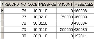
SELECT * FROM records_table


Here is the output example run from toad


You can then insert the data from an external table to your table.


CREATE TABLE in_records_table as

(SELECT * FROM records_table);


You can also set the REJECT LIMIT parameter of the external table. If Oracle found any error while processing a record, the record will be rejected. And if the number of rejected records exceeded the REJECT LIMIT parameter, your select statement will fail. You can change the REJECT LIMIT parameter by the statement


ALTER TABLE table_name REJECT LIMIT value


After processing the select statement of an external table, Oracle creates some files which are the bad file, discard file and the log file. The bad file contains all of the rejected records, while in the log file you can see Oracle activity when processing the external table like why a record was rejected. By default, these files are created in the same directory with the input file.


Another way to load data from a file to Oracle is by using the sqlldr command. You can see here for how to use the command.


Read more...

Findstr Command


Sometimes we need to count how many lines are there in a file. This could be easy if we only have to count all of the line/records in the file. But, we might need to count only records containing a certain string. We can do this with the DOS findstr and find command.


The syntax of the findstr command is


findstr "certain string" file.txt


Above is the simplest syntax to use findstr. You can see the full options list by typing /?. You can use /N to display also the line number in front of each line. You can use the /C command to search for contiguous string that contains space character. At the example above, the findstr will find every line that contain "search" or "string" in file.txt. If you use /C:"certain string", the findstr will find "certain string" in the file. You can also pipe the output to another command or redirect the output to another file.


I was once asked to count the number of records in a file of which transaction record is 200, the amount is zero, etc. Because the file is large, doing it manually will be tedious. Here's the findstr command form that I use.


findstr " 200 " file.txt | findstr /N " 0.00 " > out.txt


At the command above, I first search for the lines containing the string " 200 ", then I redirect the output to another findstr command that will search lines containing " 0.00 ". So, all the commands do is searching for lines that contain both " 200 " and " 0.00 ". In the end, the output is redirected to the out.txt file. Which after that, I can open out.txt to check for the result. With the /N option, the lines in out.txt will have line number.


I redirect the output to a file so that I can check and process further the output for another purpose. If you're sure all of the output lines are the line you want, you can pipe the output from findstr command to the find command by using the option /C.


findstr " 200 " file.txt | findstr " 0.00 " | find /C "200"


Read more...
top