EIGRP Stuck in Active

Each time there’s a change in the network (the successor path is lost) and there is no feasible successor path is available, EIGRP routers will send query message asking if there exist any other route to the unreachable network. This router, will wait for replies from all of the active EIGRP interfaces except the down link. If for some reasons, replies are not received, the missingroute will stay in Active state. The router will wait for 3 minutes before neighbor adjacencies with the neighbor router that fails to reply are reset.


When an EIGRP neighbor receives a query for a route, it behaves as follows:

  • If the EIGRP topology table does not currently contain an entry for the route, then the router immediately replies to the query with an unreachable message, stating that there is no path for this route through this neighbor.

  • If the EIGRP topology table lists the querying router as the successor for this route and a feasible successor exists, then the feasible successor is installed and the router immediately replies to the query.

  • If the EIGRP topology table lists the querying router as the successor for this route and a feasible successor does not exist, then the router queries all of its EIGRP neighbors except those sent out the same interface as its former successor. The router will not reply to the querying router until it has received a reply to all queries that it originated for this route.

  • If the query was received from a neighbor that is not the successor for this destination, then the router replies with its successor information.

The most common reasons for SIA routes are as follows:


  • The router is too busy to answer the query because of high CPU usage or memory problems, and cannot allocate the memory to process the query or build the reply packet.

  • The link between the two routers is not good; therefore, some packets are lost between the routers. While the router receives enough packets to maintain the neighbor relationship, the router does not receive all queries or replies.

  • A failure causes traffic on a link to flow in only one direction—this is called a unidirectional link.

  • Too many alternate paths through the network can create EIGRP convergence problems. This complexity creates an ideal condition for a router to become SIA as it waits for a response to queries that are being propagated through these many alternate paths.


There are two methods to solve this problem:


  • Configuring Stub Router

    A stub router sends a special peer information packet to all neighbor routers to report its status as a stub router.

    Any neighbor that receives a packet informing it of the stub status does not query the stub router for any routes but still send replies and updates to the stub router. This is different from a passive interface which deactivate EIGRP on that interface.

    To configure a router to be a stub router, first enter the EIGRP configuration level and enter the following command.

    eigrp stub [receive-only | connected | static | summary]


    receive-only: Prevents the stub from sending any type of route.

    connected: Permits stub to send connected routes (may still need to redistribute).

    static: Permits stub to send static routes (may still need to redistribute).

    summary: Permits stub to send summary routes.


    If you just enter the command eigrp stub then default parameters are connected and summary.


  • Using Route Summarization

    Another way to solve this problem is by using route summarization. When the route goes down. The router will send query messages out to its neighbors, but the receiving routers, instead of asking their neighbors about the route again, they simply say “No! I don’t have any other paths to that route because you say you have the path for all networks that start by that address.”

To disable the stuck in active timer, use the following command at the EIGRP configuration level.

timers active-time disable


Read more...

OSPF Virtual Link

Virtual links make it possible to have an area not directly connected to area 0. But, it’s recommended that you redesign your network as soon as possible to connect each non-backbone area to area 0.


Virtual links depend on router-id, that’s why it’s a good idea to set your router-id manually through the router-id command. Because this type of router-id doesn’t change except you change it to another value manually, difference from the active loopback or physical interface which may accidentally change the OSPF router id if you activate another interface which has a higher ip address than the existing one.


To configure a virtual link, go to the ABRs, R2 and R3 in the case above and go to the OSPF process configuration level and use the following command


area AREA-NUMBER virtual-link ROUTER-ID


AREA-NUMBER: the area number that both routers reside in. In the picture above, because both R2 and R3 reside in area 1, the AREA-NUMBER here should be 1..


ROUTER-ID: router-id of the other ABR that you want to associate a virtual link with.


That command should be used at both routers (both ABRs) that need to be associated with a virtual link, in this case a virtual link is needed between R2 and R3.


The virtual link makes R3 believe that it’s directly connected to area 0.


The virtual link command actually creates a tunnel between both routers, in a CCIE lab, you might be asked to create a virtual link without using the virtual-link command.


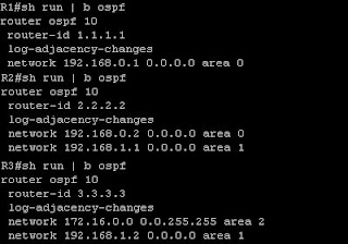
Let's try to configure virtual link based on the case above. At this point, I have configured the interfaces and OSPF at all three routers in the picture. R3 have loopback interfaces which reside on network 172.16.1.0/24, 172.16.2.0/24, 172.16.3.0/24 and all routers are running OSPF process number 10. R1 is configured with router id of 1.1.1.1, R2 is configured with router id of 2.2.2.2 and R3 is configured with router id of 3.3.3.3. But, I haven't configure a virtual link between R2 and R3. Here's the configuration of all 3 routers.


At this point, R1 doesn't have the routes to the 172.16.0.0/16 networks behind R3, However R3 have a route to network 192.168.0.0/24 which is the R1-R2 link.


Let's configure a virtual link between R2 and R3. As shown above, the configuration is simple. First we connect to R2, go to the OSPF process number 10 configuration level and enter the command "area 1 virtual-link 3.3.3.3" and at R3 go to the OSPF process number 10 configuration level and enter the command "area 1 virtual-link 2.2.2.2". Now, if we connect to R1 and do the "show ip route" command, we will see routes to 172.16.0.0/16 networks.


You can also do the "show ip ospf neighbor" command at R2 or R3 and see that they are connected through the OSPF_VL0 interface.


Read more...

OSPF LSA Types

Link State Advertisements (LSAs) are the building blocks of OSPF. You need to know about OSPF LSA because there are many OSPF area types and certain area types block certain LSA type from entering the area. There are 11 types of OSPF LSAs, these are the 5 most common OSPF LSAs:


  • Router LSA (Type 1)


  • The most common type of LSA. An advertisement about one network. Like hey, this is network 10.1.1.0/24 and here’s the cost to reach it.


  • Network LSA (DR Generated) (Type 2)


  • Only advertised by DR. Advertise all routers that are attached to the same segment (same switch/LAN) including itself. This LSA is sent to all of the routers in the area (not only to the routers in the same segment as the DR).


  • Summary LSA (ABR Summary route) (Type 3)


  • Advertisement about networks from another area. This route is marked as an IA (Inter-Area) route in the routing table.


  • Summary LSA (ASBR Location) (Type 4)


  • Advertise the ip address of the ASBR in the network. This might be needed to know the next-hop ip address for external routes.


  • External LSA (ASBR Summary route) (Type 5)

  • Advertised routes coming from an ASBR.


  • NSSA External LSA (Type 7)

  • Generated by the ASBR in an NSSA (Not-So-Stubby Area). This LSA is converted back to type 5 once it reach the backbone area


Read more...

EIGRP Authentication

An EIGRP enabled router may have authentication configured. This authentication should be the same on two routers for them to form adjacency


An EIGRP enabled router may have more than one key for authentication. This is for automated reason. So, if for example that later you decide it’s time to change the password for EIGRP authentication, you don’t have to configure all EIGRP routers all at the same time so they have the same key for authentication.


Keys in EIGRP can be given the start and end valid date. Usually you will give a short amount of time (an hour to a day) that the old key and the new key can be used (two keys are valid at a time). Say that at Dec 1st 2010, your old key will be expired and you choose a new key that will be valid at Nov 30th 2010, so that will give an error buffer, if for some reason there are some error preventing some EIGRP routers to communicate with each other.


To configure authentication in EIGRP, first you must create a key chain. In global configuration mode.


key chain WORD


WORD: the name of the keychain. Example key chain EIGRPAuth


After entering the above command, you will be inside the key-chain configuration level. Here, you can specify some keys as you like. The command is


key NUMBER


NUMBER: a number value, this is just for an identification for each key.


After you enter that command you will be in the key level configuration level. Here, you specify the string of the key (like the actual password of the key) and the send-lifetime and the accept-lifetime. Send-lifetime specifies the time when this router will send that key for authentication, the accept lifetime specifies the time when this router will be accepting that key.


The commands are


key-string WORD


accept-lifetime HH:MM:SS MONTH DATE YEAR HH:MM:SS MONTH DATE YEAR


send-lifetime HH:MM:SS MONTH DATE YEAR HH:MM:SS MONTH DATE YEAR


the first part of HH:MM:SS MONTH DATE YEAR is the start time while the second part is the end time.


A complete key chain configuration example as can be seen in a running-configuration is:


key chain EIGRPAuth
key 1
key-string student
accept-lifetime 12:00:00 Jan 1 2010 12:00:00 Jan 2 2011
send-lifetime 12:00:00 Jan 1 2010 12:00:00 Jan 2 2011
key 2
key-string cisco
accept-lifetime 12:00:00 Jan 1 2010 12:00:00 Jan 2 2011
send-lifetime 12:00:00 Jan 1 2010 12:00:00 Jan 2 2011


you must create these key chain configuration on other EIGRP routers too. To avoid setting wrong lifetime of the keys and end up with a chaos because of the different keys, you can just copy and paste this from the running-configuration and paste them on other routers.


After making those key chain, you enable the authentication per-interface basis. The commands are


ip authentication mode eigrp AS-NUMBER md5


this command turn on eigrp authentication on the interface. there’s only one mode available, which is md5 (don’t know why this command exists if there’s only one mode available).


Next step is to specify which key chain to be used for authentication. The command is


ip authentication key-chain eigrp AS-NUMBER WORD


WORD: the name of the key chain.


You must configure authentication on both routers, if one is not using authentication, the neighbor adjacency will down.


The key used to send is the first valid key sorted by the key ID. If key 1 is no longer valid to be sent, key 2 will be used instead.


Routers will receive keys based on the key id not the key string. The key ID sent should match the key ID set on the peer router.


Read more...
top