EIGRP

EIGRP is ac Cisco-propietary routing protocol, so only Cisco routers can operate this protocol. Junpier / Nortel wouldn't be able to communicate with your Cisco routers using this protocol

EIGRP is easy to use and manage, but always calculates everything because it's also the main reason of mibehaving networks using EIGRP.

EIGRP is called a hybrid protocol because it combines the feature of distant-vector protocol and link-state protocol.

EIGRP advertisement will only be advertised to the same router running EIGRP in the same autonomous system. in a cisco router when you enter the eigrp configuration, you alse specify the autonomous system number (ASN). example
router eigrp 100
this will be enter the configuration of eigrp for asn 100

EIGRP use classless routing.
EIGRP is an enhanced of IGRP (IGRP is also cisco propietary).

************
EIGRP's value
************
Hello time - most network 5 secs, NBMA 60 secs
Hold time - default three times hello time (15 / 180)

hold time = time before a router assume that the end router is down because it's not receiving hello packets anymore.

both use metrics composed of bandwidth, delay, reliability and load. both routing protocols use only bandwidth and delay.

Cisco discontinued IGRP starting with IOS 12.2(13)T and 12.2(R1s4)S.

EIGRP doesn't send periodic update and route entries do not age out. periodic packets that are send between EIGRP neighbor routers are lightweight hello. this is used to monitor the link between routers, updates are sent when changes occur (link added, or become unavailable)

EIGRP doesn't use holddown timer.
communication between EIGRP routers are sent through multicast 224.0.0.10 address.

DUAL (Diffused Update Algorithm) is the algorithm used by EIGRP. with DUAL EIGRP doesn't use hold-down timer and split horizon primarily for routing loop avoidance. EIGRP primarily use DUAL to avoid routing loop, EIGRP maintains a topology table beside the routing table. this topology table maintain the best route to a destination and any loop-free (loop-free mean that neighbor router doesn't have route for the destination network that pass through this router) backup routes. when a route become unavailable DUAL will see if any backup paths exist and enter it to the routing table.

EIGRP support routing for other layer 3 technologies beside IP, such as IPX and AppleTalk. for each of the techonology, EIGRP maintains different table. so each technology has its own topology table, routing table and neighboor table. because of this, EIGRP doesn't use TCP/UDP as its layer 4, because IPX and AppleTalk doesn't support TCP/UDP. EIGRP uses Reliable Transport Protocl (RTP). even its name is reliable, RTP can work as a reliable or unreliable

Although EIGRP refers to the parameter as an "autonomous-system" number, it actually functions as a process ID. This number is not associated with an autonomous system number discussed previously and can be assigned any 16-bit value.

******************
Metric calculation
******************
EIGRP can use Bandwidth, Delay, Reliability and Load to calculate the metric. by default only Bandwidth and delay are used for metric calculation. each factor has its own weight. each weight is presented as K1, .. K5. k's default value
K1 (bandwidth) = 1
K2 (load) = 0
K3 (delay) = 1
K4 (reliability) = 0
K5 (reliability) = 0

you can see these values on a router by entering the "show ip protocols" command.

K is the value of the metric weight, by assigning different weigh to k you can set the metric calculation to be weighed to what factor. to see the actual value used for metric calculation by entering the "show interface" command. you may see a lot information but take a look at the section similar to the following:

MTU 1500 bytes, BW 1544 Kbit, DLY 20000 usec, reliability 255/255, txload 1/255, rxload 1/255
(note MTU is not used for metric calculation)

Bandwidth - is a static value. the value of the bandwidth may or may not reflect the correct value of the physical bandwidth of the interface. the value of bandwidth in an interface can be changed. bandwidth is measured in Kbit. in most serial interfaces the default value is 1544 Kbit.

Delay - a measure of the time it takes for a packet to traverse a route (the router does not actually track how long packets are taking to reach the destination. The delay value, much like the bandwidth value, is a default value that can be changed by the network administrator). delay is measured in microseconds (usec). the value of the delay is based on the type of link to which the interface is connected. for FastEthernet link the value is 100 usec, Ethernet 100 usec, T1 (default serial) 20000 usec.

Reliability - is a measure of how rely is the link for the packet to be forwarded (how many packets are error or dropped). unlike delay, reliability is dynamically measured every 5 minutes. value of reliabilty is between 0 and 255. with 1 means minimally reliability and 255 means 100% reliable. if the value is 234/255 means that the link is 91.8% reliable.

Load - measure of how saturized is the link (amount of traffic saturizing the link). like reliability, load is calculated dynamically using 5 minutes-weighted average. of which value range from 0 - 255. in load, 1/255 is minimally loaded link (more desireable) and 255/255 means the link is completely saturated. there are two loads value tx (outgoing) and rx (ingoing).


the calculation of the metric
(K1 * bandwidth + K3 * delay) * 256

*Note: since K2, K4 and K5 are 0 then those factors are not calculated

bandwidth = (10,000,000/bandwidth)
delay = (sum of delay/10)


************
DUAL
************
DUAL - loop-free backup paths, routing loop avoidance, fast convergence
fast convergence through DUAL is achieved by the existence of loop-free backup paths

terminology
successor = a neighboring router that's used to forward the packet, this router has the least cost to reach the destination, in other words sucessor is the next hop for a route. is showed after the word via.

Feasible Distance = the lowest metric for a given route. this is showed after the administrative distance in "show ip route".

Feasible successor = a neighboring router that can reach the same destination as the successor and satisfies the feasibility condition.

Feasibility condition = a condition that the reported distance of the feasible successor to a given destination is less than the local distance (metric).

Reported Distance = metric that is advertised to other routers. this is simply a neighbor feasible distance for a destination.

a loop-free backup paths for a given destnation exists if there's another neighboring router (feasible successor) beside the current next-hop router (successor), of which metric (reported distance) for that destinatin is less than local current metric.

you may be wondering why if the feasible successor metric is less than the local current one, the router doesn't choose the path through the feasible successor? this is because the cost from current router to the feasible successor haven't been added to the reported distance of feasible successor. 'total cost' may be greater through feasible successor than
but this doesn't mean that if the successor failed, and all other neighbors RD (reported distance) is greater than this own FD (feasible distance), no route can be used to a given destination. if there is another path, and RD is greater than FD, that path will be used but it takes time for DUAL to recompute.
through successor.


auto-summary is on by default.
to make a manual summary, enter the following command at the interface level
ip summary-address eigrp  as-number network-address subnet-mask

as-number : eigrp process ID
network-address : summary network address
subnet-mask : mask for the summary

default route in EIGRP is usually set by the static route for the router that's connected to outside EIGRP network (ISP for example) and is redistributed with the router configuration command "redistribute static".
Read more...
Frame Relay is a network technology that runs on layer 2. Frame Relay is a NBMA (Non-Broadcast Multiple Access) network. Frame Relay usually used as an option for WAN connection.

***********
Topologies
***********
when connecting more than two sites, a topology must be chosen to create the connection between each sites. the Frame Relay topologies are star, full-mesh and partial-mesh.

Star (hub and spoke)
a central site acts as a hub and other remote sites act as spokes. each remote site has an access link to the central site.

Full Mesh
full mesh topology connects every site to every other.

*****
DLCI
*****
DLCI is the identifier of each VC in frame relay. DLCI is 10-bits long and there for can hold up to 1024 (0 - 1023). some DLCI number are reserved and cannot be used. those are

0 : LMI (ANSI, ITU)
1-15 : reserved for future use
992-1007 : CLLM
1008-1022 : reserved for future use (ANSI, ITU)
1019-1020 : multicasting (cisco)
1023 : LMI (cisco)


DLCI is local significance which means that it's only unique to the local. at other hop, the same DLCI number can be used to identify different VC.


************
Inverse ARP
************
ARP is used to find out the layer 2 address from a layer 3 address available. inverse ARP does the opposite.

used primarily in frame relay and ATM.

on cisco routers, inverse ARP is on by default.

Inverse ARP works as much like ARP. the frame relay router will sends an inverse ARP requests on its PVC to dscover the layer 3 adress of the remote device connected to the frame relay network.

to clear dynamically created frame relay maps that are created using inverse ARP, use the command
clear frame-relay inarp


****
LMI
****
Local Management Interface, a protocol developed by Cisco, digital equipment corporation (DEC), Northern Telecom and StrataCom. enable the DTE to communicate with the DCE and acquire information about the status of the network.

LMI is basically a keepalive mechanism. every 10 seconds or so, the end device polls the network, either requesting a dumb sequenced response or channel status information. if the network does not respong width the requested information, the user device may consider the connection to be down.

there are 3 LMI types:
- cisco
- Ansi
- Q933a (ITU standard)
starting from 11.2 IOS version, the LMI is autosensed. if it happen to manually configure the lmi type, do it with the command
frame-relay lmi-type [cisco | ansi | q933a]

if you configure the lmi type manually, you need to set the keepalive interval too. if the keepalive interval is mismatch too big. the switch can declare that the router is dead. configure the keepalive interval with the command "keepalive second". default keepalive is 10 seconds on cisco serial interface.


******************
Address Mapping
******************
dynamic mapping, dynamic mapping in frame relay is achieved from the combination of LMI and inverse ARP. LMI will acquire the active DLCI for each data link, so the router knows what DLCI that's exist. then the router will send inverse ARP request for each DLCI to acquire the corresponding network layer address.

static mapping, you can enter a static mapping for a DLCI on cisco routers. enter the command (at interface level configuration)

frame-relay map protocol protocol-address dlci [broadcast] [ietf | cisco]

protocol-address : layer 3 address
dlci : DLCI number associated for the layer 3 address
ietf : use this keyword instead of cisco when connecting a non-cisco device

you cannot use both dynamic mapping and static mapping for the same dlci and protocol. you can disable the inverse ARP protocol for an interface by entering the command

no frame-relay inverse-arp


*************
Subinterface
*************
used in frame relay to enable forwarding routing updates through a physical interface which has multiple connections (split horizon rule).

point-to-point subinterface
establish one PVC connection to another physical interface / subinterface on a remote router. acts as a point-to-point connection. has a single DLCI, each point-to-point subinterface is on its own subnet. typically, there is a seperate subnet for each point-to-point subinterface. solve the split horizon issue.

multipoint subinterface
establich multiple PVC. acts as a NBMA network. doesn't solve the split horizon issue. all the participating interface are in the same subnet.

REMEMBER
when you use the subinterface, usuall you must assign the subinterface with a DLCI number to differentiate it from the physical interface (LMI does not know about subinterfaces).

do not assign network address to the physical interface. if the physical interface has an address, frames are not received by the local subinterfaces. the required command for the physical interface is to specify the encapsulation to be used (ALL SUBINTERFACES WILL BE USING THE SAME ENCAPSULATION AS SPECIFIED AT THE PHYSICAL INTERFACE ENCAPSULATION).


*************
Flow Control
*************
frame relay switched use the FECN and BECN bit to control the flow of frames going through the network

SW1 ----------------------------------------- SW2

assume that congestion occure at the link between SW1 and SW2.

FECN bit is set for every frame going from SW1 to SW2.
BECN bit is set for every frame coming to SW1 from SW2 and is leaving on another interface.

DTE can set the DE (Discard Eligible) flag to 1. usually less important frames are marked with the DE 1. this is used to avoid more critical data to be discarded should congestion happened.


**************************
Configuring Frame Relay
**************************

needed configuration for frame-relay to work
- encapsulation frame-relay
- assign ip address to the interface

Cisco routers autosense the LMI type used. recall that there are three LMI types: Cisco, ANSI Annex D and Q933-A Annex A. the default LMI type for cisco routers is cisco.

you can configure subinterfaces with the command
interface serial number.sub-number multipoint | point-to-point

number = the physical port number
sub-number = subinterface number. to make troubleshooting easier, use the DLCI as the subinterface number.
multipoint | point-to-point = specify the type of the subinterface


to assign a subinterface its DLCI use the following command
frame-relay interface-dlci dlci-number

dlci-number = the number of the DLCI you wished to be associated with the subinterface.

Read more...

Switch:Basic

CSMA/CD
Carrier Sense : before transmitting, each device sense the media if there's another data being transmitted.
Multiple Access : in ethernet, the distance between devices maybe too long that one device couldn't detect the data sent from another and both device may transmit data at the same time.
Collision Detection : when a collision is detected, by unnormal amlitude. devices run a random backoff time and start transmitting again.

Full-duplex switches do not use CSMA/CD, because full-duplex communication has their own Tx and Rx line. this is not the case if the line is half-duplex (see autonegotiation).


Ethernet uses CRC as its checksum


Auto-MDIX
with auto-MDIX enabled, you can use either straight-through or crossover to connect devices to the switch.
The auto-MDIX feature is enabled by default on switches running Cisco IOS Release 12.2(18)SE or later. For releases between Cisco IOS Release 12.1(14)EA1 and 12.2(18)SE, the auto-MDIX feature is disabled by default.

propagation delay => the time needed for a packet to travel through the media from the source to the destination. (about 0.556 microseconds per 100 m for Cat 5 UTP.)

latency => the overall time needed for a packet to travel from its source to the destination. source of latency can come from three sources, 1. the time the NIC needs to put voltage pulses on the wire, 2. the propagation delay, 3. the time for the devices on the way to process the packets.


Switch Packet Forwarding methods
Store-and-Forward : the switch first store the data in the buffer until the full frame receive before forwarding it. (Cisco switches use this mechanism). when the frame is in the buffer, the switch will check for error with CRC. store-and-forward is needed for QoS analysis where frame classification for traffic prioritization is necessary.
Cut-through : the switch acts upon the data as soon as the data is received. the switch only buffers the destination address for CAM table lookup and then forward the packets. this mehcanism doesn't do error checking. there are two types of cut-through, fast-forward -> forward the frame only by seeing the first 6 bytes (Destination address) and fragment-free -> stores the first 64 bytes, The reason fragment-free switching stores only the first 64 bytes of the frame is that most network errors and collisions occur during the first 64 bytes.


layer 3 switching : as layer 2 lan performs switching by analyzing the MAC address correspondends to which port, layer 3 switching analyze the IP address is associated to which interface.
Routers perform additional Layer 3 services that Layer 3 switches are not capable of performing. Routers are also capable of performing packet forwarding tasks not found on Layer 3 switches, such as establishing remote access connections to remote networks and devices. Dedicated routers are more flexible in their support of WAN interface cards (WIC), making them the preferred, and sometimes only, choice for connecting to a WAN. Layer 3 switches can provide basic routing functions in a LAN and reduce the need for dedicated routers.


*******
Booting
*******
The boot loader finds the Cisco IOS image on the switch by first looking in a directory that has the same name as the image file (excluding the .bin extension). If it does not find it there, the boot loader software searches each subdirectory before continuing the search in the original directory.

IOS initializes the interface using the Cisco IOS commands found in the operating system configuration file named config.text, stored in the switch flash memory

The boot loader also provides access into the switch if the operating system cannot be used. The boot loader has a command-line facility that provides access to the files stored on Flash memory before the operating system is loaded. From the boot loader command line you can enter commands to format the flash file system, reinstall the operating system software image, or recover from a lost or forgotten password.

When the switch is on, the POST begins. During POST, the LEDs blink while a series of tests determine that the switch is functioning properly. When the POST has completed, the SYST LED rapidly blinks green. If the switch fails POST, the SYST LED turns amber. When a switch fails the POST test, it is necessary to repair the switch.


you can show the last 10 command that you've entered by entering the command "show history". you can change the size of history commands by entering "terminal history size 50" at the privileEXEC mode.


********************
Configuring a switch
********************
to remotely access a switch you must assign the switch an IP address.

good practice is not to use VLAN 1 as the management vlan.

you need to configure a default-gateway to the switch, so it can forward packets to other LAN from the command prompt of the switch. to do this enter the command
ip default-gateway gateway-address
gateway-address : the ip address of the router

configure duplex and speed
duplex auto
speed auto

network adminstrator can manage the CAM table. enter "show mac-address-tabe" to see what's inside the CAM table. you can configure the aging time of the MAC address learned from receiving port (default is 300secs) and you can also assign a static MAC address to a specific port (static MAC addresses don't aged out by time) by entering
mac-address-table static vlan (1-4096, ALL)interface interface-id

: static MAC address you wich to assign
(1-4096, ALL) : vlan number
interface-id : interface type and number

you can copy your running-configuration to the flash (as a backup, so that you can save more than one configuration by entering the command
copy running-configuration flash:filename
filename : the name of the file you wish. example, config.bak1

then you can delete the files saved in flash by entering the following command
delete flash:filename

you can also erase the startup-configuration in nvram by entering
erase nvram
erase startup-configuration

***************
Switch security
***************

you can set password to line connection (console, vty) on a switch by entering "password the-password" at the line level configuration and by entering "login" you enable the authentication process. (however the password can be seen by vewing the running-configuration file)

you can set password needed to access the privilegeEXEC mode by entering one of the two commands
enable password password
enable secret password
but, if you use the "enable password" command, the password is not encrypted and can be viewed in the running-configuration file. when you enter both command the password from "enable secret" is the one that's used.

you can apply access-list to the line connection similar applying access-list to interfaces by entering "access-class". the difference is that interface use the "access-group" command.

vty lines (you may have up to 16 vty lines, 0 - 15) are telnet by default you can change it to SSH (there are some version of SSH, use SSHv2 because it use stronger encryption than SSHv1) enter "transport input ssh" at the line configuration level. you can also enter "transport input all" to enable telnet and ssh connection.

SSH communication use DES, 3DES (algorithm used usually specified by client). and needs RSA keys which involve public key and private key. SSH server should provide public key to make a switch serves a public key enter "crpyto key generate rsa" at global configuration level

to overcome the issue of viewing the password in the configuration file. you can use the encrypted password service by entering "service password-encryption" at global configuration level. the encryption that's used is called type 7, this is a weak encryption and there are tools to crack password encrypted with this encryption.

to recover password (if you accidentally happen to forget your password) you need to get access to the switch from console, actually the step is booting the switch and enter the helper mode, rename the config.text file so the switch doesn't load the configuration, after you're inside rename the config.text back. and change your old password.


you can set banner on line connection, "banner login" will be shown before the username and password prompt is presented.


***********************
Common Security Attacks
***********************
-MAC flooding
-fake DHCP server (spoofed gateway)
-CDP attack, from CDP attacker can inspect the version of the device and search for vulnerabilities.
-Telnet attacks - Brute force, DoS (vulnerability at telnet server).


*************
Port Security
*************
allow you to strict which MAC addresses are able to connect using the port to the switch.
3 ways to configure port security
- static secure MAC addresses: you specify the MAC addresses allowed to connect to the port. mac addresses configured this way are stored in the address table and the running-configuration on the switch. enter the command "switchport port-securit mac-address theAddress" at the interface configuration level.
- dynamic secure MAC addresses: MAC addresses are learned dynamically and stored only in the address table. MAC addresses are removed when the switch restarts. enter the command "switchport port-security" at the interface configuration level.
- Sticky secure MAC addresses: MAC addresses are learned dynamically and saved in the running-configuration. enter "switchport port-security mac-address sticky" at the interface configuration level.

enter "switchport port-security maximum number" at the interface configuration level to set the maximum number of MAC address learned to the interface.

violation occurs when
-maximum MAC addresses (default maximum mac address learned is 1) learned is reached and new MAC address attempts to access the interface.
-the same MAC address has been learned / configured on a secure interface and is seen on another secure interface in the same VLAN.

change violation modes by entering "switchport port-security violation [protect | restrict | shutdown]"
security violation modes
- protect: frames from unknown source addresses are dropped. you're not notified of the violations occured.
- restrict: frames are dropped, syslog message is logged, violation counter increments.
- shutdown: frames are dropped, syslog message created, port is shutdowned, violation counter increments. (this is the default mode)


"show port-security interface interface-id" to see port security status on that interface
"show port-security address" to see the secure MAC addresses table


a good practice is to shutdown unused port. you can use the "interface range" command to shutdown a range of ports.

Read more...
OSPF (Open Shortest Path First) is one of the routing protocol most used. It's a link state routing protocol.

OSPF use bandwidth as its metric. The algorithm it uses to calculate the metric is to divide 100,000,000 by the bandwidth that the link has in bps, so a 100 Mbps link will have a metric value of 1.

OSPF forces you to design the network by dividing it into areas, there are two main type of area backbone area (usually called area 0) and nonbackbone area. OSPF also support different type of network in fact that there are different type of networks like point to point, broadcast (ehternet, Token Ring, FDDI), nonbroadcast (framerelay), etc..


there are also different kind of routers in OSPF. Designated Router is the router that do the brunt of the OSPF processing. DR and Backup DR is elected in every area (in every area - not so sure about this) through a complicated way (ospf priority, highest loopback ip, highest ip address assigned to this router)

usually a router running OSPF has a loopback interface to prevent the election of the DR through the highest physical ip address.

OSPF routers don't send routes instead they send link state advertisement (LSA). there are different kinds of LSA. Router LSA is sent by every OSPF router, Network LSA is sent by DR, and etc...

so, when you're configuring a network with OSPF (remember that OSPF is a classless routing protocol) you specify which area this network will be in.
example:
network 10.10.10.0 0.0.0.255 area 0


the complexity of OSPF is one of the reasons that many people choose EIGRP instead. but remember that EIGRP is only implemented by cisco routers.

routes redistributed into OSPF is divided into two 2 types. E1 routes increase the metric of the route as it is propagated through OSPF router (added cost at each hop). while E2 routes have its metric the same for all routers.

Routes from different AS is a E2 route.


routes summarization
Inter-Area
enter the following command in ABR router (Area Border). to announce the summary route to other OSPF areas
area xxx range A.B.C.D yyy.yyy.yyy.yyy

xxx : area of the summary route
A.B.C.D : ip address of the summary
yyy.yyy.yyy.yyy : subnet mask of the summary

for example an OSPF area 4 has the following subnet
172.16.100.16
172.16.100.32
172.16.100.48
172.16.100.60
in this example the summary address is 172.16.100.0 255.255.255.192 . then enter the following command to the ABR router of thearea
area 4 range 172.16.100.0 255.255.255.192


Inter-Domain
enter the following command to the ABR
summary-address A.B.C.D yyy.yyy.yyy.yyy

A.B.C.D : ip address of the summary
yyy.yyy.yyy.yyy : subnet mask of the summary


OSPF doesn't support IPX


*********************
OSPF default values
*********************
Hello time - 10 (multiaccess and point-to-point), 30 on NBMA
Dead time - 40 (dead time is the time for OSPF to wait before declaring the end router is down).

in order for two router establishing an adjacency, both router must have the same timers value and network type. those parameter is
-hello interval
-dead interval
-network type

five network types in OSPF:
- point-to-point
- broadcast multiaccess
- nonbroadcast multiaccess (NBMA)
- point-to-multipoint
- virtual links


OSPF multicast address:
224.0.0.5 = all ospf routers
224.0.0.6 = all DR routers

OSPF DOES NOT AUTOMATICALLY SUMMARIZE SUBNET AT MAJOR NETWORK BOUNDARY.


five types of OSPF LSPs(Link State Packets)
1.Hello - used to maintain adjacency with other OSPF routers.
2.DBD - Database Description, sent to other OSPF routers that contains an abbreviated list of the sending router's link-state database and used by the receiving routers to check against the local link-state database.
3.LSR - Link State Request, sent to request more information about any entry in the DBD.
4.LSU - Link State Update, used to reply LSR and to announce new information.
5.LSAck - Acknowledgement to LSU.


OSPF calculates the metric using the bandwidth of the link. the calculation is taken as per 100mbps, so if a link bandwidth is 100mbps then the cost is 1. you can change the reference-bandwidth the ospf command "auto-cost reference-bandwidth" (measured in mbps). it's good practice to change the reference-bandwidth on all router running ospf when you change it on a router.

ALTERNATIVELY, you can set a cost for an interface in OSPF without OSPF needing to calculate the cost anymore by entering the following command at interface level configuration:
ip ospf cost xxx

xxx : the number of the cost


DR - BDR

DR and BDR election is happen only in multiaccess network.

election of DR & BDR happen as soon as an interface of a router participate in OSPF routing. this can happen when a router boot up or a network command for an interface is enabled. because of this, a router with a lower ip address (or routerID) could be the DR if it happened to be the first router running OSPF that boots. once a router become a DR, it will be a DR until it fails, or interface shutdown.

election process:
1. DR: router with the highest OSPF interface priority.
2. BDR: router with the second highest OSPF interface priority
3. if OSPF interface priorities are equal, the highest router'ID is used to break the tie.

Determining router ID
1. use the IP address configured with the "router-id" command.
2. use the highest loopback interface address.
3. use the ACTIVE (interface must be in an up-up state, but not neccessarily included in OSPF activity) physical IP address.


YOU CAN CHANGE THE VALUE OF OSPF INTERFACE PRIORITY by entering the following command at interface level configuration
ip ospf priority (0-255)
because OSPF interface priority is set on interface level. it can be set that a router be the DR on a network and a DRother on another network.


every link on an OSPF has a state. this state tell us about it's status with the other end device.

"show ip ospf neighbor" can show you about neighbor OSPF routers, their status as DR/BDR/DRother and their state with the local router (2WAY / FULL). 2WAY is adjacency between DRother routers they don't send LSA to each other just hello packets, FULL is adjacency between DROther and DR.


router ospf process-id is a number between 1-65535. the process-id is only locally significant, means that it may differ between router running OSPF to establish an adjacency. this is different with EIGRP that the autonomous-number DOES NEED to match to form a neighboring.

When two routers have the same router ID in an OSPF, domain routing may not function properly. If the router ID is the same on two neighboring routers, the neighbor establishment may not occur.

Like RIP, OSPF requires the use of the "default-information originate" command to advertise the 0.0.0.0/0 static default route to the other routers in the area

Read more...

VLAN

VLAN means Virtual LAN.  a VLAN is as much the same as a subnet.
Computers connected to a switch doesn't mean that they can communicate, they must be in the same vlan (subnet). for computer in different network (subnet/vlan ) to communicate a layer 3 device is needed. however, we can create internetwork without VLAN.


VLAN advantages:
-Security : data are not cannot travel cross vlans except they are meant to.
-Higher performance : vlan create seperate broadcast domain, host that is not logically in the same domain won't receive broadcast traffic.
-Improved IT staff efficiency : vlan makes IT staff works easier, because each network has similar function.


VLAN characteristics
-vland id 1 - 10005 are normal range IDs. (stored in the vlan.dat file in flash memory)
-1 and 1002 - 1005 (1002-1005 are reserved for token ring and FDDI VLANs) are automatically created and cannot be removed.
-1006-4094 are extended vlan, designed for sevice provider (stored in the running configuration file)

VLAN types
Data vlan : traffic generated by users. it's common practice to seperate voice traffic and management traffic from user's data traffic.
Default vlan : the default vlan id assigned to ports when the port is up. this make any devices connected to the port can communicate to each other and become in one broadcast domain. in Cisco this is vlan 1. securit best practice is to change the default vlan other than vlan 1.
Native vlan : assigned to trunk port. according to IEEE, native vlan designed to maintain backward compatibility with untagged traffic (old LAN scenario). for our purposes we call native vlan a comon identifier on opposing end of trunk-link. best practice is to set native vlan other than vlan 1.
Management vlan : management vlan is used for administrator to connect to the switch, as switch is a layer 2 address, we create a vlan interface so that we can remotely connect to the switch by assigning an ip address to the vlan interface. and also because traffic only forwarde to the same vlan, computer attached to another vlan port won't be able to access the management vlan.
Voice vlan : voice vlan is needed because voice traffic require low latency. you can tag vlan for voice traffic. this can be achieved because cisco ip phone is a switch, it can communicate with the switch it's connected to and prioritize voice traffice.

Switchport membership modes
Static mode : manually assigned a port belongs to which vlan.
Dynamic mode : port vlan configuration is handled by a VMPS (Vlan Membership Policy Server) based on the MAC address connected to the port.
Voice vlan : a port can be assigned to a data vlan and void vlan if an IPphone is connected to it. example to configure the port connected to an IPphone on a switch

interface fas 0/18
mls qos trust cos
switchport voice vlan 150
switchport mode access
switchport access vlan 20
end

from the example configuration, void vlan is assigned to vlan id 150, data vlan is assigned to vlan 20.


********
TRUNK
********
Trunk link is used to carry traffic from more than one vlan. trunk doesn't belong to a specific vlan, rather that it's a conduit for vlans between switches and routers.

ISL is legacy of cisco trunking technology, today only 802.1Q trunking that's used.

when frame forwarded through a trunk link, more information is needed to know from which vlan does the frame belongs to (ordinary ethernet frame doesn't contain vlan information). this is accomplished by encapsulating the frame with a header that contains vlan information, that is 802.1Q frame tagging. inside the header that is vlan id and ethertype

Native Vlan & Trunk in 802.1Q
Native vlan is the vlan that traffic from native vlan will pass through trunk link untagged (isn't encapsulated with 802.1Q header). when a trunk port receive an untagged frame, it will forwarded to the default PVID (Port Vlan ID) which is the id of the native vlan. native vlan behaviour, receive tagged frame: drop the traffic


to configure native vlan on a trunk port

switchport trunk native vlanID

vlanID : id of vlan that will be the native vlan


Dynamic Trunking Protocol (DTP) is cisco propietary, other switches from different vendors don't support DTP. DTP modes
ON : command "swicthport mode trunk". the port sends DTP frames periodically. the port then will become a trunk port whatever the other end is set to be.
dynamic auto : command "switchport mode trunk auto". the port sends DTP frames periodically, telling that the port can be a trunk port but doesn't request the other end to make a trunk connection. this port will be a trunk only if the other end request this port to be trunk.
dynamic desirable : command "switchport mode trunk desirable", the port sends DTP frames periodically, telling the other end that it's able to be in a trunking state and asks the other end to be in a trunking state, if the other end is able to be in a trunking state (with mode of on / desirable / auto), this port will be a trunk port, if the other end is set to nonegotiate this port will remain access port (not a trunk port).
nonegotiate : command "switchport nonegotiate" this will turn off DTP, no DTP frame will be sent out. this port won't be a trunk port through DTP negotiation. BUT USE THIS MODE TO ESTABLISH A TRUNK LINK WITH A SWITCH FROM OTHER VENDORS.

enter the command "show dtp interface" to determine the current mode configured.

******************
VLAN Commands
******************
Creating vlans
There are two ways to create a vlan in a cisco catalyst switch, through the vlan database and global configuration. database configuration is being phased out in favor of global configuration.
commands in global configuration level

vlan vlanid
name word


vlanid = number of the vlan


Deleting a vlan / vlans
to delete a single vlan use the command

no vlan vlanid


to delete entire vlan in the vlan.dat file use the command

delete flash:vlan.dat


Assigning port to a vlan
first, configure the port mode to be an access port, then assign the vlan id to the port
commands in interface configuration level

switchport mode access
switchport access vlan vlanid


Removing port from a vlan
command in interface configuration level

no switchport access vlan


Set allowed vlan on a trunk
command in interface configuration level

switchport trunk allowed vlan add vlan-id

vlan-id : the vlan ids that are allowed to pass this trunk link. example
10, 20, 30 (allow vlan 10, 20 and 30 to pass the trunk link)


************************************
Common Vlan Error Configuration
************************************
Native vlan mismatches : This configuration error generates console notifications, causes control and management traffic to be misdirected and, as you have learned, poses a security risk.
Trunk mode mismatches : This configuration error causes the trunk link to stop working.
Allowed Vlans on trunks : In this situation, unexpected traffic or no traffic is being sent over the trunk.
Vlan on different subnet : every host in the same vlan must be in the same subnet.


Read more...

RIP

RIPv1
RIPv1 is a classfull routing protocol. CLASSFULL ROUTING DOESN'T INCLUDE THE SUBNET MASK INFORMATION IN ITS ROUTING INFORMATION UPDATES. because RIP is a classful routing. when you enter a subnetted network, the IOS will automatically convert it to the corresponding classful network. for example, network 192.168.1.32 will be converted to 192.168.1.0. Because of this behaviour, there is a design issue in RIP. there shouldn't be two subnetted networks with the same classful network address reached by different interface (discontiguous subnet) from a router. RIP advertise classful network. the routing table entry in this router will be unstable (if the cost of both subnets are the same) or this router will send the packets load balanced through each route (because there are two entries for the same major network).

RIPv1 broadcast its routing entires through update packets. a single update packet, can hold up to 25 routing entries.

RIP implements split horizon, so routes learned from an interface is not sent when sending updates to that interface.

you can stop a router running a routing protocol (the command discussed next is supported by all routing protocol), in this case RIP, from sending routing advertisement such as periodic updates to an interface by entering the following command at router's global configuration level.

passive-interface interface-type interface-number

interface-type : type of the interface (FastEthernet, Serial, ..).
interface-number: number of the interface.

you might want to enter this in a case where there's no neighbor router running the same routing protocol on that interface.

Routers running RIPv1 are limited to using the same subnet mask for all subnets with the same classful network.

************
RIP Timers
************
RIP use periodic updates to update its routing table. therefore there are some timers associated with RIP. Here are the timers

Periodic Updates - 30 secs
Invalid Timer - 180 secs. if a route is not refreshed up to 180secs. the route is marked invalid by making it unreachable (rip do this by changing the metric to 16)
Flush Timer - 240 secs. 60 secs longer than invalid time. after flush timer expires, the route is removed from the routing table.
Holddown Timer - 180 secs. if a router learns about a route from another router that it's unreachable, the route still stay in the routing table up to the holddown timer before it's removed to give time for every router to learn about the unreachable route. any advertisement with the same or worse metric reporting the route will be ignored. however, if an advertisement telling a better metric, the entry will be renewed and the holddown timer will be cleared.

RIPv1 sends updates to 255.255.255.255, which means a local broadcast address. any router will block packets destined to this destination from going out.

however RIP might recognize a subnet network. examine the following routing table.

172.30.0.0/24 is subnetted, 3 subnets
R 172.30.1.0 [120/1] via 172.30.2.1, 00:00:03, Serial0/0/0
C 172.30.2.0 is directly connected, Serial0/0/0
C 172.30.3.0 is directly connected, FastEthernet0/0

You can see that the route to 172.30.1.0 is gotten from R (RIP). How can RIP know that this network's subnet mask is 24? this can happen if the network advertised and the interface that received the advertisement have the same major network (classful network). in this case, the interface receiving the 172.30.1.0 advertisement has an ip address with network id of 172.30.x.x

RIP may have more than one route for a destination, if there's more than one route with equal cost to the same destination. RIP will use one of these for load balancing. if you enter "show ip protocols" command. you can see this information in the RIP section.

Maximum path: 4

this means that there can be up to 4 redundant equal cost path to the same destination.


Boundary Router : any router with interfaces in more than one major classful network.
boundary router may want to summarize the subnets of one major network to another major network (in fact that RIP only advertise major networks)

if the route entry for an update sent out to a different major network interface. then the network addres in the route entry is summarized to the classful network and then advertised. so the in the receiving router, the entry in the routing table for those subnets is only one, that is the major network of the subnets.

when an RIP interface first come up, it will sent a request message to neighboor routers. neigboor routers running RIP will send response message to the requesting router. it evaluates each route entry. If a route entry is new, the receiving router installs the route in the routing table. If the route is already in the table, the existing entry is replaced if the new entry has a better hop count. The startup router then sends a triggered update out all RIP-enabled interfaces containing its own routing table so that RIP neighbors can be informed of any new routes.

RIP doesn't support VLSM either. in a case where there are subnets from the same major network is applied with different subnets. only the subnets with the same subnet mask as the interface address of the outgoing update are advertised.

Supernet route will not be advertised by classful routing protocol including RIP. imagine in a case that you're creating a static default route with the destination address is a supernet. and you want RIP to redistribute this default route through the "redistribute static" command. however, because it's a supernet route, that default route won't be advertised to neighboring routers.

if you want to propagate static default route through RIP, you can enter the following command at the router configuration level

default-information originate


RIPv2
classles routing protocol

A ROUTER RUNNING RIPv1 CAN STILL PROCESS AN RIPv2 MESSAGE, IT WILL JUST IGNORE RIPv2 SPECIFIC FIELD.

RIPv2 Message (packet) contains subnet information, next-hop (The Next Hop address is used to identify a better next-hop address).


Read more...
Distance Vector Routing Protocol, as the name implies,
Distance : how far the destination from this router.
Vector     : the direction to forward the packet to the destination
DV RP doesn't know the full path to reach the destination, it only know how far the destination is, and the direction of the destination.

Terminology
Split Horizon - that a router should not advertise a network through the interface from which the update came.
Poison routing - a way for DV router to make a route removed from a table of neighboring router by making the metric of the route to be unreachable.

RIP
Routing Information Protocol (RIP) was originally specified in RFC 1058. It has the following key characteristics:
- Hop count is used as the metric for path selection.
- If the hop count for a network is greater than 15, RIP cannot supply a route to that network.
- Routing updates are broadcast or multicast every 30 seconds, by default.


EIGRP
Enhanced IGRP (EIGRP) is a Cisco proprietary distance vector routing protocol. EIGRP has these key characteristics:
- It can perform unequal cost load balancing.
- It uses Diffusing Update Algorithm (DUAL) to calculate the shortest path.
- There are no periodic updates as with RIP and IGRP. Routing updates are sent only when there is a change in the topology.


Read more...

IOS is the abbreviation of Internetworking Operating System. IOS is the operating system most used in Cisco's routers and switches. In my opinion IOS is designed to be easy to use. There are helps for the commands, and most of the 
commands are simple enough. Here i'll give a demonstratin of how to configure a Cisco router running 
IOS as it's operating system.

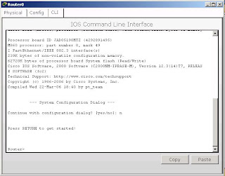
First you may want to understand how IOS is structured. IOS is structured hierarchically. When you first enter the IOS you will be given a command prompt similar to this


you will be given the prompt Router>. "Router" is the name of the router you're logged on. And the ">" tells you that you're in the user mode. In the 
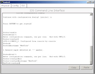
user mode you can only run limited commands, you can't configure the router. You can enter the exec/privileged mode by entering the command "enable". Then you'll be given the prompt Router#. You may notice that the ">" is changed to "#" this tells you that you are in the exec mode. In privileged mode you can enter more commands than in user mode and also you can do some debugging here. But still, no configuration can be made in this mode.

Then you can enter the configuration mode from the exec mode by entering the command "configuration terminal". After you enter the command you may notice the change of the prompt to Router(config)#. Here you are at the global configuration mode (i will explain later why it is called global configuration) and you can enter some configuration to the router. For example you can change the name of the router to something 
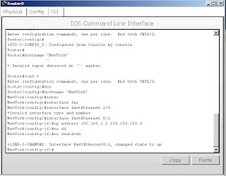
meaningfull. You may enter the command "hostname router-name" with router-name is the name of the router that you want. After you changed the name of the router, the changed will be reflected at the prompt


You may see at the picture above, that i've changed the name of the router to "NewYork". Then maybe you want to configure one of the interface of the router. Let's say that you want to configure the fastEthernet 1/0 interface. First thing that you've got to do is to enter the interface fastEthernet 1/0 configuration level. Because you're at the global configuration mode, you can enter the interface configuration mode by entering the command "interface interface-type slot-number" because we want to configure the fastEthernet 1/0 interface then we enter "interface fastEthernet 1/0" command. You may see the change of the mode by seeing the prompt given. Usually some basic things people do is to give an ip address to the interface and activate the interface. To give an ip address to the interface you enter the command "ip address 192.168.1.1" you may want to change the 192.168.1.1 part to any ip address you want. Then enter the "no shutdown" command to activate the interface.


Remember that i said IOS is structured hierarchically. If you remember the modes you've been before reaching the interface configuration mode. Than you might have the idea of the hierarchy. First time you enter a router, you will be at the user mode. So the hierarchy is user mode -> exec mode -> global configuration mode -> interface level configuration mode. You've seen how to enter each mode. Then you might be wondering how to go up one level in the hierarchy, to do this you can enter the command "exit" command.

The configuration that you have made are saved to the running-configuration file. What does it mean? Cisco routers have two configuration files. One is saved in the RAM and the other is in the NVRAM. Running-configuration file is the one that in the RAM. This means that if you restart the router or the router
is turned off accidentally, the changes you've made are gone. To save the configuration to be permanent enter the command "copy running-config startup-config" at the exec mode. After entering the command you will be asked for the destination file name, enter "startup-config" as the name.

There are still so many other comands available in IOS. Hope this can give you some understanding of how IOS works.


Read more...
top