OSPF: Authentication over a Virtual Link


In OSPF, we can have an area that is not directly connected to the backbone area by using the virtual link feature. If somehow, OSPF authentication is enabled in area 0. Routers that is connected through a virtual link must have the authentication configured too. This is because the router believe that it is directly connected to the area 0, and since routers in area 0 authenticate themselves for communicating, the virtual-linked router would no longer able to communicate with the routers in area 0.


The command to configure authentication on a virtual-link is:


area NUMBER virtual-link A.B.C.D message-digest-key NUMBER2 md5 WORD


NUMBER: the area number where both virtual-linked routers reside.

A.B.C.D: the router-id of the peer router.
NUMBER2: the id number of the digest key.
WORD: the authentication password used.


So, let's say that we have this topology


We have an md5 authentication configured in area 0 with password of "cisco". To configure this authentication for area 0, go to all router in area 0, which in this case are R1 and R2 and type the following command (assume that you are from the global configuration level and the OSPF process id is 1):


router ospf 1
area 0 authentication message-digest
interface fastethernet1/0
ip ospf authentication message-digest
ip ospf message-digest-key 1 md5 cisco


Now, since authentication is in place for area 0, in order for area 2 to have connectivity with the rest of OSPF network, the authentication should be configured on the virtual-linked routers too, which in this case are R2 and R3. We first go to R2 and go to its OSPF process 1 configuration level and enter the following command


area 1 virtual-link 3.3.3.3 message-digest-key 1 md5 cisco


Next we go to R3, go to the OSPF process 1 configuration level and enter the command:


area 1 virtual-link 2.2.2.2 message-digest-key 1 md5 cisco
area 0 authentication message-digest


We need to configure the command "area 0 authentication message-digest" on R3 to avoid authentication type mismatch error (Type 0 - Null authentication on R3, and Type 2 - Message Digest authentication on R2). This is because a virtual-link is a tunnel that makes as if R3 is directly connected to area 0, and since area 0 is configured with message-digest authentication, therefore R3 should be configured to use message-digest authentication too on area 0.


Read more...

PPP Multilink Connection


PPP Multilink connection adds load-balancing and to your PPP connection. PPP multilink sends packet in fragments spread


To configure PPP Multilink connection is first go to your serial interfaces that will participate in your PPP link perform no-shutdown and change the encapsulation to PPP.


no shutdown
encapsulation ppp


Then configure the logical multilink interface. You create the multilink interface, give it an IP address, and specify the encapsulation for it. On global configuration level, type this command


interface multilink NUMBER


NUMBER: this could be any unique number you want to identifiy the multilink interface.


ip addresss A.B.C.D NETMASK


A.B.C.D: IPv4 address for this interface

NETMASK: the subnet mask for the IPv4 address.


encapsulation ppp


Next, you want to configure something that can link your logical multilink interface to your physical serial PPP interfaces. This something is done with the multilink-group command. Type the following command at your multilink and physical serial interface configuration level.


ppp multilink-group NUMBER


NUMBER: the number of the multilink group.


The number configured should be the same at the multilink interface and the physical serial interfaces.


By this time, you should be able to ping your PPP peer. You can verify your multilink interface with the command "show ip interface brief" and "show ppp multilink". Here is the output of the show ppp multilink command:


Read more...


There are 5 network tpyes in OSPF. They are: NBMA (Non-Broadcast MultiAccess), Point-to-Multipoint which are RFC standard and Broadcast, Point-to-Point, Point-to-Multipoint (static) which are Cisco proprietary. The default network type for interfaces in OSPF for multipoint network or when you are configuring Frame-Relay on physical interfaces is NBMA.


The characteristics of NBMA network type are there will be DR/BDR elections, what has to be noted here is that DR and BDR should have direct connectivity with the rest OSPF router in the network. In NBMA network there will be no broadcast, so that we have to define our OSPF neighbor statically. We only have to specify the neighbors statically at one router (one-way), and the peer router will respond and the neighborship will be formed. Usually, the static neighbor configuration is done at the hub-router.


We will try to configure OSPF in NBMA network type based on this topology


First, configure the serial1/0 interface, give an ip address, set the encapsulation to frame-relay and perform no shutdown


ip address 10.10.10.1 255.255.255.0
encapsulation frame-relay
no shutdown
ip ospf priority 255


Remember that in an NBMA network, there is a DR/BDR election. DR/BDR routers should have direct connectivity with the rest of the routers in the segment. So here, we want to make sure that R1 becomes the DR router. Therefore we set the OSPF priority of the interface to 255. You can go to R2 and R3 and configure the same configuration at the serial1/0 interface


R2:


ip address 10.10.10.2 255.255.255.0
encapsulation frame-relay
no shutdown
ip ospf priority 0


R3:


ip address 10.10.10.3 255.255.255.0
encapsulation frame-relay
no shutdown
ip ospf priority 0


R2 and R3 have no direct connectivity, therefore both of them couldn't be the BDR. We specify the OSPF interface priority of R2 and R3 serial1/0 to 0, making them inelligible for DR/BDR election.


I also configure a loopback0 interface on R1 for OSPF connectivity purpose, so if later after OSPF has been configured, we can see at least a route learned from OSPF on R2 and R3 in its routing table. On R1:


interface loopback0
ip address 10.10.10.3 255.255.255.0


Then we can start configuring OSPF. We will use OSPF with process id of 1.


R1:


router ospf 1
router-id 1.1.1.1
network 10.10.10.1 0.0.0.0 area 0
network 192.168.1.0 0.0.0.255 area 0


R2:


router ospf 1
router-id 2.2.2.2
network 10.10.10.2 0.0.0.0 area 0


R3:


router ospf 1
router-id 3.3.3.3
network 10.10.10.3 0.0.0.0 area 0


You can do the "show ip ospf interface" command to see the network type of serial1/0 interface. Here's the partial output of the command.


It should list the network type as NON_BROADCAST. If not, you can change the OSPF network type with the command "ip ospf network non-broadcast" at the interface configuration command level. At this point, you will not have any OSPF neighbor, since in non-broadcast network, neighbors should be specified manually. Remember that we only have to type the neighbor command one-way, only on one router and it is a good idea to configure it at the hub-router, which is R1. So, we go to R1 and type in the following command at the global configuration level:


router ospf 1
neighbor 10.10.10.2
neighbor 10.10.10.3


After entering the command, you can type the "show ip ospf neighbor" command to see that R1 is ATTEMPT-ing to become neighbor with R2 and R3. You might want to wait before the neighbor status becomes FULL. When it comes to FULL, we can verify that the network of R1 loopback0 interface is advertised to R2 and R3 and is listed in their routing table. From the picture bellow, for you who might be wondering why does 192.168.1.1 as advertised as a host route with /32 subnet mask when you expect it to be /24. This is because loopback interfaces are advertised with /24 subnet. To get a /24 network in the routing table, the OSPF network type of the loopback interface could be change to point-point with the command "ip ospf network point-to-point".


But, there is still a problem. If you try to ping R3 from R2 and vice-versa, the ping will fail. This is because both R2 and R3 think that they have direct connectivity because both of the reside in the same network. But actually, they have to send the packets to R1 first before reaching each other. To solve this, we add the manual frame-relay map command for them to reach each other using the DLCI used to reach R1. On R2 serial1/0 interface configuration level, type the following command:


frame-relay map ip 10.10.10.3 201 broadcast


On R3 serial1/0 interface configuration level, type the following command:


frame-relay map ip 10.10.10.2 301 broadcast


Now, if you try to ping R3 from R2 or vice-versa, the ping will succeed.


Read more...

PPP Enhancements


There are some enhancements that you can do for your PPP connection. These enhancements including compressions and reliability.


To configure PPP compression, go to your PPP interface and type (it could only compress in some IOS)


compresssion WORD


WORD: the type of PPP compression you want to use.


There are three compression type to compress data portion of PPP packets. These are:


  • MPPC. Microsoft mode

  • Predictor. This type of compression uses more memory than processor.

  • Stac. This compression uses more processor than memory.


When deciding which compression you want to use, you can decide based on your router's memory and processor. If you have more free memory than processor in your router, it could be best for you to go for the predictor compression. The same goes for if you have more processor resource than memory, you may want to go for stac. And as you may have guessed, you should configure compression on both sides of the connection for the PPP link to work.


TCP Header Compression


You can also compress TCP packet header compression for your PPP link. To configure this, go to your PPP interface configuration level and type (you might want to assign an ip address to the interface first before issuing this command)


ip tcp header-compression


PPP Reliabilty


If there would be many UDP packets go through the PPP link. You can add reliability down at the layer 2 link of PPP connection. This will give error correction and error detection at your PPP connection. To configure this, type the following command at your PPP interface


ppp reliable-link


PPP Minimum Quality


You can specify the minimum quality of your PPP connection in percentage. If for some cases, your successfull traffic goes bellow the minimum quality number you have specified for your PPP connection. Your router will pro-actively tear down the connection and try to reconnect. To configure this, type the following command at your PPP interface


ppp quality NUMBER


NUMBER: the percentage number of your minimum quality


Read more...

VLAN Access Map


VLAN Access Map gives you the ability to control traffic between users in the same VLAN. It is configured in the same way as a route map is configured. If you have VLAN 100 of which subnet is 192.168.100.0/24, and you want to deny access from host 192.168.100.10 to host 192.168.100.20. Here is how you configure your switch.


First, you create the VLAN map. In the global configuration mode, enter the command “vlan access-map” the syntax of the command is


Vlan access-map WORD NUMBER


WORD: the name of the access-map
NUMBER: the sequence number of the statement. You can later insert another statements with sequence number lower or higher than your current one.


After you enter the “vlan access-map” command, you will be in the access-map configuration level. Here, you can specify what to match and the action is, just like a route-map.


If you enter the command match and hit the question mark, you will be listed by two options, ip and mac. You guessed it, you can permit or deny access based on ip address or the mac address. We need to create an access-list, either ip access-list or mac access-list, that match the criteria of what we need to be matched. We will create the access-list later, but here we will configure the access-map to match ip access-list numbered 101. and the action is to drop (the action is either drop or forward. Drop for deny and forward for permit) the packet.


Match ip address 101

Action drop


For this scenario, you will want to match the ip of source 192.168.100.10 and destination 192.168.100.20. Therefore, we will create an ip access-list numbered 101 as what it is the access-list number we have configured in the access-map. Exit the access-map configuration and enter access-list command.


Access-list 101 permit ip host 192.168.100.10 host 192.168.100.20


The last thing to do is to apply to which vlan does the access-map applies to. To do this, we use the command “vlan filter” at the global configuration mode. The syntax is


Vlan filter WORD vlan-list NUMBER


WORD: the name of the access-map
NUMBER: the number of the vlan you want the access-map to be applied to. You could use a number for the vlan or a vlan list for more than one vlan.


Read more...

Spanning-Tree Enhancements


Portfast

Immediately change a port into a forwarding port. Can be used for ports that are connected to end devices. Should always be paired with BPDU guard. With BPDU guard enabled on a switch, if that switch received a BPDU from a portfast port, it will shutdown the port


PortFast Configuration
go to the interface configuration level


spanning-tree portfast


BPDU Guard configuration
in the global configuration level


spanning-tree portfast bpduguard


There’s another feature other than BPDUguard, called BPDU-Filter, if a BPDU was received by the switch on a portfast port, the BPDU will just be ignored.


UplinkFast

Not much used anymore. Uplink fast provides a way to make a blocked port change into a forwarding port in case that the root port is down.


UpLinkFast Configuration:
go to the interface configuration level


spanning-tree uplinkfast


BackBone Fast

When a root port of a switch is down, there could be a chance the switch thinks that the root bridge is down, while it’s actually not. When this happens, the switch will send BPDUs with its own switch priority and and MAC address as the root bridge, if this ever happens and received by another switch on which the Backbone fast is enabled, this switch will pro-actively tell the switch that assume it is the root bridge that the root bridge is still alive by sending a BPDU back to that switch with the real Root Bridge ID.


BackBoneFast Configuration:
go to the interface configuration level


spanning-tree backbonefast


Read more...

Modifying AD Schema


If for example you're asked to add a new attribute to the user class in your Domain, you can do this by modifying your AD Schema. Modifying AD schema is not always about adding new attributes, you can also add new class or modify existing ones and also activate or deactivate class and attributes. Before you make a modification to the AD Schema, you have to make sure that you're have the permission to do so. To check this, your account must be a member of the Schema Admin group.


Microsoft has provides you a tool to make AD Schema modification. You can access this tool from the MMC.


First, type the MMC on the Run command. This will bring you up the MMC window,


go to File > Add/Remove Snap-in. Click the Add button. Choose the Active Directory Schema from the list and click Add (If you don't see the Active Directory Schema in the list, you have to regist it first by typing the 'regsvr32 schmmgmt.dll' at the Run command or at the command prompt).


Click close and the Active Directory Schema utility will be added to the MMC. There's only one domain controller on which AD schema changes can be made, this domain controller is called the schema master. To be able to make changes to the AD schema, this tool must point to schema master. Right click on the Active Directory Schema entry in the MMC and choose Change Domain Controller.


In this tool, you can create/modify, activate/deactivate classes or attributes. Let's say that you want to add another attribute to the user class. First, right click on the Attributes and choose Create Attribute, a dialog box will appear warning you that creating an attribute is a nonreversible action. Next, you will see the create new attribute dialog.


Common Name This field becomes the Common Name attribute of the attribute.

LDAP Display Name This is the string that the LDAP utility will display to users when they access the directory.

Unique X.500 Object ID This is the OID you received from the ISO.

Description This optional field provides a short description of the attribute.


Snytax is the data type of the attribute will hold, such as string, SID, OID, etc...

Maximum specify the maximum value for the attribute

Minimum specify the minimum value for the attribute


Now, if you ever have to create a new class or attribute, you will need a unique Object Identifier (OID). There are a couple ways to get this OID, you can apply to ANSI which will take time and money (you will have the right to use any OID that starts with your OID) or you can use the script available here (copy the script and paste it into a file with an extension of .vbs or just simply named it oidgen.vbs, then just execute the file to obtain your OID). After filling all of the needed fields, click OK.


Now, to add the newly created attribute to the user class, go to the click the Classes and search for the user class, right click on it and choose Properties. Go to the Attributes tab and click Add.


Choose the attribute that you've created and click OK. Then you can verify that the attribute is listed in the optional attribute list box.


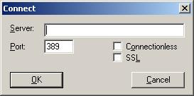
The next thing is to give values to your new attribute. There are some ways to do this, but one of the way is buy using ldp.exe. It is a tool that is included when you install Windows Server 2003 Support Tools. With this tool you can search, modify, add, delete against LDAP server such as Microsoft AD. Just type ldp on the Run command. Click on the Connection then Connect.


Type in the server location, this could be a dns name or ip address. Then just press OK. Next, we have to bind, click Connection then Bind.


Type in your username and password which has the permission to modify user's attribute, then press OK. Then click Browse then Modify.


  • In the DN textbox, type the DN for the user which you want to modify his/her attribute. For example, the DN for the administrator account would be something like this CN=administrator,CN=users,DC=srv1,DC=domain,DC=com.

  • In the attribute textbox, type in the name of the attribute that you want to modify. For example, if you want to modify the givenName of a user, type in givenName.

  • Type in the new value for the attribute that you want to change in the Values textbox.

  • Press enter, you can add another new attribute and value again if you want to modify more than one attribute.

  • If you're done then click Run.


To verify the attribute modification use the search operation agains AD, press Ctrl+S or click Browse then Search in LDP.


Read more...

Fetch Data from Multiple Records

You can use function to fetch data from multiple records into one field. If for example we have table users and hobbies.


user_id
user_name
address
1 John Walker Bangladesh
2 Frank McLane Nepal
3 Leon Kennedy USA


user_id
hobby
1Reading
1 Sleeping
1 Walking
2 Swimming
3 Help People

If we're asked to display the user's name along with his/her hobbies, first we create a function to fetch the hobbies of a user into a single column. The function is as follows


CREATE FUNCTION [dbo].[get_hobbies]

(
@usr_id int
)
RETURNS varchar(255)
AS
BEGIN
DECLARE @hobbies varchar(255)
DECLARE @temp varchar(255)

SET @hobbies = ''
SET @temp = ''

DECLARE HbCur CURSOR FOR SELECT hobby FROM users inner join hobbies on users.[user_id] = hobbies.[user_id] WHERE users.[user_id]=@usr_id

OPEN HbCur
FETCH next FROM HbCur INTO @temp
WHILE @@Fetch_Status = 0
BEGIN
SET @hobbies = @hobbies + @temp + ', '
FETCH next FROM HbCur INTO @temp
END


CLOSE HbCur
DEALLOCATE HbCur

--remove the last unnecessary comma
SET @hobbies = substring(@hobbies, 1, len(@hobbies)-1)

RETURN @hobbies
END


The function is quite self-explanatory. The body of the function starts after the keyword BEGIN and end at the END keyword. It takes the user_id as a parameter which will be used to select all hobbies of that user. Here, two variables are declared, @hobbies and @temp. These two variables are used to store the result of the hobbies queried. Next, we declare a CURSOR that will hold the result hobbies from the query, and then can be iterated to get each hobby. Next, there is a loop which will fetch every single hobby to the @temp variable which will then be appended to @hobbies variable that will hold all of the hobbies separated by comma. Last, the function returns all of the hobbies.


To test the function you can run the following sql


SELECT [dbo].[get_hobbies] (1)


This is the output when I run the query.


Read more...

ORACLE: Load Data from a File

If you're asked to load data from a file in Oracle, you can use the external tables. External tables allow you to query data from a file and treat it almost like a table (there are some limitations to external tables such as you can't create index, you can't INSERT or UPDATE an external tables). Let's practice through an example.


Let's say that we have this csv file named records.csv


76,10,0110,0.00,460008
77,10,0210,350000.00,460009
78,30,0110,0.00,430084
79,10,0110,500000.00,430085
80,30,0110,0.00,497014


The first step is to determine which folder you want this file to be put into. What you should concern here is that Oracle should have the read and write access right to the file. For this example, we create a new directory in 'C:\Data'. After physically creating the directory, we then create a directory in Oracle


CREATE DIRECTORY records_dir AS 'C:\Data';


Here, records_dir is the unique name of the directory, you can name you directory to something else.


Then we create the table which defines the external table. In the CREATE TABLE statement, we define what fields are in the external table, where is the directory for the external table, the filename, etc.. For this example we create a table named records_table


CREATE TABLE records_table (

record_no int,

code int,

message varchar2(4),

amount number(8,2),

message2 varchar(6)

)

ORGANIZATION EXTERNAL (

DEFAULT DIRECTORY records_dir

ACCESS PARAMETERS (

records delimited by newline

fields terminated by ','

)

LOCATION ('records.csv')

);


Because the file is a csv file, we define the terminating character for each field as ','. External table can also load data from a fixed column file.


We can then select the data from the external table by using the SELECT statement (you can also add the WHERE clause)


SELECT * FROM records_table


Here is the output example run from toad


You can then insert the data from an external table to your table.


CREATE TABLE in_records_table as

(SELECT * FROM records_table);


You can also set the REJECT LIMIT parameter of the external table. If Oracle found any error while processing a record, the record will be rejected. And if the number of rejected records exceeded the REJECT LIMIT parameter, your select statement will fail. You can change the REJECT LIMIT parameter by the statement


ALTER TABLE table_name REJECT LIMIT value


After processing the select statement of an external table, Oracle creates some files which are the bad file, discard file and the log file. The bad file contains all of the rejected records, while in the log file you can see Oracle activity when processing the external table like why a record was rejected. By default, these files are created in the same directory with the input file.


Another way to load data from a file to Oracle is by using the sqlldr command. You can see here for how to use the command.


Read more...

Findstr Command


Sometimes we need to count how many lines are there in a file. This could be easy if we only have to count all of the line/records in the file. But, we might need to count only records containing a certain string. We can do this with the DOS findstr and find command.


The syntax of the findstr command is


findstr "certain string" file.txt


Above is the simplest syntax to use findstr. You can see the full options list by typing /?. You can use /N to display also the line number in front of each line. You can use the /C command to search for contiguous string that contains space character. At the example above, the findstr will find every line that contain "search" or "string" in file.txt. If you use /C:"certain string", the findstr will find "certain string" in the file. You can also pipe the output to another command or redirect the output to another file.


I was once asked to count the number of records in a file of which transaction record is 200, the amount is zero, etc. Because the file is large, doing it manually will be tedious. Here's the findstr command form that I use.


findstr " 200 " file.txt | findstr /N " 0.00 " > out.txt


At the command above, I first search for the lines containing the string " 200 ", then I redirect the output to another findstr command that will search lines containing " 0.00 ". So, all the commands do is searching for lines that contain both " 200 " and " 0.00 ". In the end, the output is redirected to the out.txt file. Which after that, I can open out.txt to check for the result. With the /N option, the lines in out.txt will have line number.


I redirect the output to a file so that I can check and process further the output for another purpose. If you're sure all of the output lines are the line you want, you can pipe the output from findstr command to the find command by using the option /C.


findstr " 200 " file.txt | findstr " 0.00 " | find /C "200"


Read more...

SQL: Selecting Columns from Different Rows

There might be times when you have to show values from different records as a row. This could for reporting need and based on the design of the table in the database. Let's say that you have a table that looks like the following:

NameTax Type Number1Number2
Roy Raphael HousingNULL5000
Sam Murphy Medical1000NULL
Sam Muprhy HousingNULL3000
Roy Raphael Medical800NULL

If you want to display the sum all of the tax types for a single person in a row, one way to do this is by using the case keyword. This article assume that there's only two tax types in the table. So, no query for dynamic number of columns is covered. The expected result could be like the following:

NameHousingMedical
Roy Raphael 5000800
Sam Murphy 30001000


By using the case keyword, we can filter which data will be put to which column.


select sum(case when col1 = 'value' then col2 end) as ps-column

In the case above, if the Tax Type value is 'Housing' we put it in pseudo-column named Housing and so we do the same for the Medical tax. The end result of the query might be:


select [name], sum(case when [Tax Type] = 'Housing' then isnull(Cost, 0) end) as Housing, sum(case when [Tax Type] = 'Medical' then isnull(Cost, 0) end) as Medical from taxes group by [name]

The above sql language is a specific sql for SQL server. The isnull function is used so that the sum will just treat null values as 0.


Read more...

Configuring SSH

Always use SSH, telnet is gone.


Configuring SSH includes configuring a domain name (ip domain-name WORD), generate rsa key (crypto key generate rsa), specify only ssh for vty connection (transport input ssh), specify where to find username and password list (login WORD. This could be local, if you use local, you will want to create username and password in the router)


First you have to configure a domain name for your router with the command (enter this command at the global configuration level)


ip domain-name WORD


WORD: the domain name string.


Then you generate rsa key by the command


crypto key generate rsa [general-keys | usage-keys]


In the picture above, when you try to create an rsa key, there will be two parameters


  1. General-keys. By default Cisco routers use the same key for all encryption (SSH, HTTPS, …)

  2. Usage-keys. Usage-keys create a unique key.


Bit range of an rsa key is 360bits – 2048bits. A minimum of 1024 is usually used. For old series router (2500, 2600 series), generating an rsa key could take a long time (10 – 15 minutes).


You can configure some ssh options through the command (from the global configuration level)


ip ssh time-out NUMBER


NUMBER: in sec, 1-120 secs.


ip ssh authentication retries NUMBER


NUMBER: 0-5 retries


Read more...

Configuring SNMP

Simple Network Management protocol is good to gather information per interface basis. SNMP version 1 and 2 doesn’t support authentication. SNMP version 1 is an old protocol, it doesn’t support to monitor Gigs link. SNMP version 2 was out primarily to support that problem so that you can monitor high bandwidth link even there are some other enhancements to the SNMP version 1. SNMP version 3 added security. It adds authentication and encryption.


The following command configure SNMP version 1 or 2c.


snmp-server community WORD [ACL] [ro | rw]


WORD: the community string for the snmp community (server).

ro: allow other device (server) from this community to only read information from this router. Usually you will want to use this mode.

rw
: allow other device to read and write information to this device.

ACL: you can use ACL to specify which devices can access the community string with ro | rw mode. So you can specify, devices coming from this address has the rw mode or something like that. Here you either specify the number of the ACL or the name of the ACL.


SNMP works like this, the community string is the only identifier that you need to access SNMP information from the router and it is sent in clear text. So if anybody else send an SNMP request message to the router with the right community string, then the router agrees to give SNMP information to that person.


Management Information Basis (MIB). This is the string that identify what information that you want to access or change if it is in Read-Write mode from the device. It could be in number or string representation. Let’s say that the SNMP server requested information from your router identified with MIB as 1.2.3.6.9.12, that series of number is an identifier for a specific information in your router. Maybe that’s the identifier to get the hostname, bandwidth utilization or the enable secret information. Cisco has its own MIB.


You can configure what MIB people can access in your router by the following configuration (if you don’t specify this, every information could be collected from your router)


snmp-server view STRING


to configure SNMP v3, first you have to configure the local ID for the router by the command


snmp-server engineID local HEX


HEX: hexadecimal (0-9, A-F) value with a minimum of 10 chars. Actually the HEX value is a fixed length string. It’s 16 chars fixed, if you only type 10 chars, Cisco will automatically fill the rest with 0.


Then you want to configure the SNMP group


snmp-server group WORD v3 [auth | noauth | piv]


Here, you name the group (SNMP_CROWS), specify the version that it use and specify if you want users to be authenticated to access this SNMP group (auth) and if you want to use encryption to send SNMP packets in this group (priv).


After that, you configure the users for the SNMP groups


snmp-server user WORD1 WORD2 v3 {auth [md5 | sha] WORD3} {priv [3des | des | aes] WORD4}


WORD1: the name of the user.

WORD2: the name of the group that the user belongs to.

WORD3: the password for the authentication.

WORD4: the privacy password for the user.


In this command you kinda map the user to the SNMP group, you specify that this SNMP will use v3. Note that this command still has other parameters.


If you choose to use authentication, you will want to choose the hashing method. It is either md5 or sha. Then enter what password is required by the users to access this SNMP GROUP


If you choose to use encryption (priv) you specify the encryption method and the encryption key. The available encryption methods are 3des, des, aes. which is not strong enough for an encryption but is better than not using any encryption at all.


You can also specify if you want to use ACL to limit what addresses that this USER GROUP will come from.


Read more...

EIGRP Stuck in Active

Each time there’s a change in the network (the successor path is lost) and there is no feasible successor path is available, EIGRP routers will send query message asking if there exist any other route to the unreachable network. This router, will wait for replies from all of the active EIGRP interfaces except the down link. If for some reasons, replies are not received, the missingroute will stay in Active state. The router will wait for 3 minutes before neighbor adjacencies with the neighbor router that fails to reply are reset.


When an EIGRP neighbor receives a query for a route, it behaves as follows:

  • If the EIGRP topology table does not currently contain an entry for the route, then the router immediately replies to the query with an unreachable message, stating that there is no path for this route through this neighbor.

  • If the EIGRP topology table lists the querying router as the successor for this route and a feasible successor exists, then the feasible successor is installed and the router immediately replies to the query.

  • If the EIGRP topology table lists the querying router as the successor for this route and a feasible successor does not exist, then the router queries all of its EIGRP neighbors except those sent out the same interface as its former successor. The router will not reply to the querying router until it has received a reply to all queries that it originated for this route.

  • If the query was received from a neighbor that is not the successor for this destination, then the router replies with its successor information.

The most common reasons for SIA routes are as follows:


  • The router is too busy to answer the query because of high CPU usage or memory problems, and cannot allocate the memory to process the query or build the reply packet.

  • The link between the two routers is not good; therefore, some packets are lost between the routers. While the router receives enough packets to maintain the neighbor relationship, the router does not receive all queries or replies.

  • A failure causes traffic on a link to flow in only one direction—this is called a unidirectional link.

  • Too many alternate paths through the network can create EIGRP convergence problems. This complexity creates an ideal condition for a router to become SIA as it waits for a response to queries that are being propagated through these many alternate paths.


There are two methods to solve this problem:


  • Configuring Stub Router

    A stub router sends a special peer information packet to all neighbor routers to report its status as a stub router.

    Any neighbor that receives a packet informing it of the stub status does not query the stub router for any routes but still send replies and updates to the stub router. This is different from a passive interface which deactivate EIGRP on that interface.

    To configure a router to be a stub router, first enter the EIGRP configuration level and enter the following command.

    eigrp stub [receive-only | connected | static | summary]


    receive-only: Prevents the stub from sending any type of route.

    connected: Permits stub to send connected routes (may still need to redistribute).

    static: Permits stub to send static routes (may still need to redistribute).

    summary: Permits stub to send summary routes.


    If you just enter the command eigrp stub then default parameters are connected and summary.


  • Using Route Summarization

    Another way to solve this problem is by using route summarization. When the route goes down. The router will send query messages out to its neighbors, but the receiving routers, instead of asking their neighbors about the route again, they simply say “No! I don’t have any other paths to that route because you say you have the path for all networks that start by that address.”

To disable the stuck in active timer, use the following command at the EIGRP configuration level.


timers active-time disable


Read more...

OSPF Virtual Link

Virtual links make it possible to have an area not directly connected to area 0. But, it’s recommended that you redesign your network as soon as possible to connect each non-backbone area to area 0.


Virtual links depend on router-id, that’s why it’s a good idea to set your router-id manually through the router-id command. Because this type of router-id doesn’t change except you change it to another value manually, difference from the active loopback or physical interface which may accidentally change the OSPF router id if you activate another interface which has a higher ip address than the existing one.


To configure a virtual link, go to the ABRs, R2 and R3 in the case above and go to the OSPF process configuration level and use the following command


area AREA-NUMBER virtual-link ROUTER-ID


AREA-NUMBER: the area number that both routers reside in. In the picture above, because both R2 and R3 reside in area 1, the AREA-NUMBER here should be 1..


ROUTER-ID: router-id of the other ABR that you want to associate a virtual link with.


That command should be used at both routers (both ABRs) that need to be associated with a virtual link, in this case a virtual link is needed between R2 and R3.


The virtual link makes R3 believe that it’s directly connected to area 0.


The virtual link command actually creates a tunnel between both routers, in a CCIE lab, you might be asked to create a virtual link without using the virtual-link command.


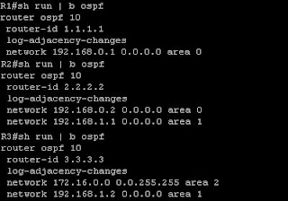
Let's try to configure virtual link based on the case above. At this point, I have configured the interfaces and OSPF at all three routers in the picture. R3 have loopback interfaces which reside on network 172.16.1.0/24, 172.16.2.0/24, 172.16.3.0/24 and all routers are running OSPF process number 10. R1 is configured with router id of 1.1.1.1, R2 is configured with router id of 2.2.2.2 and R3 is configured with router id of 3.3.3.3. But, I haven't configure a virtual link between R2 and R3. Here's the configuration of all 3 routers.


At this point, R1 doesn't have the routes to the 172.16.0.0/16 networks behind R3, However R3 have a route to network 192.168.0.0/24 which is the R1-R2 link.


Let's configure a virtual link between R2 and R3. As shown above, the configuration is simple. First we connect to R2, go to the OSPF process number 10 configuration level and enter the command "area 1 virtual-link 3.3.3.3" and at R3 go to the OSPF process number 10 configuration level and enter the command "area 1 virtual-link 2.2.2.2". Now, if we connect to R1 and do the "show ip route" command, we will see routes to 172.16.0.0/16 networks.


You can also do the "show ip ospf neighbor" command at R2 or R3 and see that they are connected through the OSPF_VL0 interface.


Read more...

OSPF LSA Types

Link State Advertisements (LSAs) are the building blocks of OSPF. You need to know about OSPF LSA because there are many OSPF area types and certain area types block certain LSA type from entering the area. There are 11 types of OSPF LSAs, these are the 5 most common OSPF LSAs:


  • Router LSA (Type 1)


  • The most common type of LSA. An advertisement about one network. Like hey, this is network 10.1.1.0/24 and here’s the cost to reach it.


  • Network LSA (DR Generated) (Type 2)


  • Only advertised by DR. Advertise all routers that are attached to the same segment (same switch/LAN) including itself. This LSA is sent to all of the routers in the area (not only to the routers in the same segment as the DR).


  • Summary LSA (ABR Summary route) (Type 3)


  • Advertisement about networks from another area. This route is marked as an IA (Inter-Area) route in the routing table.


  • Summary LSA (ASBR Location) (Type 4)


  • Advertise the ip address of the ASBR in the network. This might be needed to know the next-hop ip address for external routes.


  • External LSA (ASBR Summary route) (Type 5)

  • Advertised routes coming from an ASBR.


  • NSSA External LSA (Type 7)

  • Generated by the ASBR in an NSSA (Not-So-Stubby Area). This LSA is converted back to type 5 once it reach the backbone area


Read more...

EIGRP Authentication

An EIGRP enabled router may have authentication configured. This authentication should be the same on two routers for them to form adjacency


An EIGRP enabled router may have more than one key for authentication. This is for automated reason. So, if for example that later you decide it’s time to change the password for EIGRP authentication, you don’t have to configure all EIGRP routers all at the same time so they have the same key for authentication.


Keys in EIGRP can be given the start and end valid date. Usually you will give a short amount of time (an hour to a day) that the old key and the new key can be used (two keys are valid at a time). Say that at Dec 1st 2010, your old key will be expired and you choose a new key that will be valid at Nov 30th 2010, so that will give an error buffer, if for some reason there are some error preventing some EIGRP routers to communicate with each other.


To configure authentication in EIGRP, first you must create a key chain. In global configuration mode.


key chain WORD


WORD: the name of the keychain. Example key chain EIGRPAuth


After entering the above command, you will be inside the key-chain configuration level. Here, you can specify some keys as you like. The command is


key NUMBER


NUMBER: a number value, this is just for an identification for each key.


After you enter that command you will be in the key level configuration level. Here, you specify the string of the key (like the actual password of the key) and the send-lifetime and the accept-lifetime. Send-lifetime specifies the time when this router will send that key for authentication, the accept lifetime specifies the time when this router will be accepting that key.


The commands are


key-string WORD


accept-lifetime HH:MM:SS MONTH DATE YEAR HH:MM:SS MONTH DATE YEAR


send-lifetime HH:MM:SS MONTH DATE YEAR HH:MM:SS MONTH DATE YEAR


the first part of HH:MM:SS MONTH DATE YEAR is the start time while the second part is the end time.


A complete key chain configuration example as can be seen in a running-configuration is:


key chain EIGRPAuth
key 1
key-string student
accept-lifetime 12:00:00 Jan 1 2010 12:00:00 Jan 2 2011
send-lifetime 12:00:00 Jan 1 2010 12:00:00 Jan 2 2011
key 2
key-string cisco
accept-lifetime 12:00:00 Jan 1 2010 12:00:00 Jan 2 2011
send-lifetime 12:00:00 Jan 1 2010 12:00:00 Jan 2 2011


you must create these key chain configuration on other EIGRP routers too. To avoid setting wrong lifetime of the keys and end up with a chaos because of the different keys, you can just copy and paste this from the running-configuration and paste them on other routers.


After making those key chain, you enable the authentication per-interface basis. The commands are


ip authentication mode eigrp AS-NUMBER md5


this command turn on eigrp authentication on the interface. there’s only one mode available, which is md5 (don’t know why this command exists if there’s only one mode available).


Next step is to specify which key chain to be used for authentication. The command is


ip authentication key-chain eigrp AS-NUMBER WORD


WORD: the name of the key chain.


You must configure authentication on both routers, if one is not using authentication, the neighbor adjacency will down.


The key used to send is the first valid key sorted by the key ID. If key 1 is no longer valid to be sent, key 2 will be used instead.


Routers will receive keys based on the key id not the key string. The key ID sent should match the key ID set on the peer router.


Read more...

Password Construction

Password is one important aspect in computer security. A Password is usually used to enter user-level accounts, email accounts, web accounts, etc. With the "Remember Password" feature available in some applications, it is important to have a strong password. First there will be a list of bad password characteristics, then there will be a list of that a good password like.


Bad password characterisitcs:


  • Password with less than 8 characters.

  • Password that is using words that can be found in dictionaries.

  • Generic word passwords, such as one of your family member's name, your friend's name, computer jargon and etc.

  • Birth date, address or phone number password.

  • Password with word pattern, such as qwerty, 123321, aabbcc, and etc.

  • Words spelled backwards, such as drowssap.

  • Password with a famous people name, your idol or something.

  • Words prepended or appended with a number, such as password1, 2password.


Strong password characteristics:


  • Contains number, punctuation and letter (0-9, !@#$%^&*(),./).

  • Contains small and capital letters.

  • Longer than 8 characters.

  • Is not a word in any language or jargon.

  • Not based on any private information like your birthday, family name, etc.


There are ways to form an easy to remember strong password, you can create an acronym from a phrase. Never write your password anywhere, do not talk about it with anyone. It's usually a bad idea to use the "Remember Password" feature as available in some web browsers. Saved passwords can be viewed by other people if they have access to your computer. In Firefox (Windows version), you can go to Tools > Options... > Security > Saved Passwords and click Show Passwords to see pairs of username and password saved for certain website.


For an organization, you can ask your emplyees to never use tha same password they use in internal for their public account (public email or social network account for example). Change your and your employee's password periodically, somwhere between three to six months is an acceptable interval, but this depends on your organization's policy. Monitor your employee password, you can periodically try to break their password using an available software that can be used to brute force someone password, if on of your employee password can be guessed, ask him to change his password.


Read more...

Duties of a System Administrator


Linux involves much more than merely sitting down and turning on the machine. Linux is quite different from the most popular commercial operating systems in a number of ways, but it is no more difficult to learn.

Make no mistake: Every computer in the world has a system administrator. It may be — and probably is — that the majority of system administrators are probably those who decided what software and peripherals were bundled with the machine when it was shipped. By its very nature as a modern, multiuser operating system, Linux requires a degree of administration greater than that of less robust home market systems. By definition, the Linux system administrator is the person who has “root” access, which is to say the one who is the system’s “super user” (or root user). A standard Linux user is limited as to the things he or she can do with the underlying engine of the system.


Installing and Configuring Servers
In the Linux world, the word “server” has a meaning that is broader than you might be used to. For instance, the standard Red Hat Linux graphical user interface (GUI) requires a graphical layer called XFree86. This is a server. It runs even on a standalonemachine with one user account. It must be configured. (Fortunately, Red HatLinux has made this a simple and painless part of installation on all but the mostobscure combinations of video card and monitor; gone are the days of anguishconfiguring a graphical desktop.). Likewise, printing in Linux takes place only after you have configured a print server. Again, this has become so easy as to be nearly trivial. And Whenever a server is connected to machines outside your physical control, security issues arise. You want users to have easy access to the things they need, but you don’t want to open up the system you’re administering to the whole wide world.


Installing and Configuring Application Software
Since Linux is multiuser operating system. Each user has (or shares) an account on the system, be it on a separate machine or on a single machine with multiple accounts. While it is possible for individual users to install some applications in their home directories — drive space set aside for their own files and customizations — these applications are not available to other users without the intervention of the system administrator.

Creating and Maintaining User Accounts
An account must be created for each user and — you guessed it — no one but the system administrator may do this. That’s simple enough. But there’s more, and it involves decisions that either you or your company must make. To what may specific users have access? It might be that there are aspects of your business that make World Wide Web access desirable, but you don’t want everyone spending their working hours surfing the Web. What to do about old accounts? Perhaps someone has left the company. What happens to his or her account? You probably don’t want him or her to continue to have access to the company network. On the other hand, you don’t want to simply delete the account, perhaps to discover later that essential data resided nowhere else.


Backing Up and Restoring Files
There is a need to back up important files so that in the event of a failure of hardware, security, or administration, the system can be up and running again with minimal disruption. Only the system administrator may do this. Once you’ve decided what to back up, you need to decide how frequently you want to perform backups and whether you wish to maintain a series of incremental backups — adding only the files that have changed since the last backup — or multiple full backups, and when these backups are to be performed — do you trust an automated, unattended process?


Monitoring and Tuning Performance
System tuning is an ongoing process aided by a variety of diagnostic and monitoring tools. Some performance decisions are made at installation time, while others are added or tweaked later. A good example is the use of the hdparm utility, which can increase throughput in IDE drives considerably — but for some highspeed modes a check of system logs will show that faulty or inexpensive cables can, in combination with hdparm, produce an enormity of nondestructive but systemslowing errors.

Configuring a Secure System
For any machine that is connected to any other machine, security means hardening against attack and making certain that no one is using your machine as a platform for launching attacks against others. If you are running Web, ftp, or mail servers, it means giving access to those who are entitled to it while locking out everyone else. It means making sure that passwords are not easily guessed and not made available to unauthorized persons, that disgruntled former employees no longer have access to the system, and that no unauthorized person may copy files from your machine or machines.


Read more...
top