OSPF: Authentication over a Virtual Link


In OSPF, we can have an area that is not directly connected to the backbone area by using the virtual link feature. If somehow, OSPF authentication is enabled in area 0. Routers that is connected through a virtual link must have the authentication configured too. This is because the router believe that it is directly connected to the area 0, and since routers in area 0 authenticate themselves for communicating, the virtual-linked router would no longer able to communicate with the routers in area 0.


The command to configure authentication on a virtual-link is:


area NUMBER virtual-link A.B.C.D message-digest-key NUMBER2 md5 WORD


NUMBER: the area number where both virtual-linked routers reside.

A.B.C.D: the router-id of the peer router.
NUMBER2: the id number of the digest key.
WORD: the authentication password used.


So, let's say that we have this topology


We have an md5 authentication configured in area 0 with password of "cisco". To configure this authentication for area 0, go to all router in area 0, which in this case are R1 and R2 and type the following command (assume that you are from the global configuration level and the OSPF process id is 1):


router ospf 1
area 0 authentication message-digest
interface fastethernet1/0
ip ospf authentication message-digest
ip ospf message-digest-key 1 md5 cisco


Now, since authentication is in place for area 0, in order for area 2 to have connectivity with the rest of OSPF network, the authentication should be configured on the virtual-linked routers too, which in this case are R2 and R3. We first go to R2 and go to its OSPF process 1 configuration level and enter the following command


area 1 virtual-link 3.3.3.3 message-digest-key 1 md5 cisco


Next we go to R3, go to the OSPF process 1 configuration level and enter the command:


area 1 virtual-link 2.2.2.2 message-digest-key 1 md5 cisco
area 0 authentication message-digest


We need to configure the command "area 0 authentication message-digest" on R3 to avoid authentication type mismatch error (Type 0 - Null authentication on R3, and Type 2 - Message Digest authentication on R2). This is because a virtual-link is a tunnel that makes as if R3 is directly connected to area 0, and since area 0 is configured with message-digest authentication, therefore R3 should be configured to use message-digest authentication too on area 0.


Read more...

PPP Multilink Connection


PPP Multilink connection adds load-balancing and to your PPP connection. PPP multilink sends packet in fragments spread


To configure PPP Multilink connection is first go to your serial interfaces that will participate in your PPP link perform no-shutdown and change the encapsulation to PPP.


no shutdown
encapsulation ppp


Then configure the logical multilink interface. You create the multilink interface, give it an IP address, and specify the encapsulation for it. On global configuration level, type this command


interface multilink NUMBER


NUMBER: this could be any unique number you want to identifiy the multilink interface.


ip addresss A.B.C.D NETMASK


A.B.C.D: IPv4 address for this interface

NETMASK: the subnet mask for the IPv4 address.


encapsulation ppp


Next, you want to configure something that can link your logical multilink interface to your physical serial PPP interfaces. This something is done with the multilink-group command. Type the following command at your multilink and physical serial interface configuration level.


ppp multilink-group NUMBER


NUMBER: the number of the multilink group.


The number configured should be the same at the multilink interface and the physical serial interfaces.


By this time, you should be able to ping your PPP peer. You can verify your multilink interface with the command "show ip interface brief" and "show ppp multilink". Here is the output of the show ppp multilink command:


Read more...


There are 5 network tpyes in OSPF. They are: NBMA (Non-Broadcast MultiAccess), Point-to-Multipoint which are RFC standard and Broadcast, Point-to-Point, Point-to-Multipoint (static) which are Cisco proprietary. The default network type for interfaces in OSPF for multipoint network or when you are configuring Frame-Relay on physical interfaces is NBMA.


The characteristics of NBMA network type are there will be DR/BDR elections, what has to be noted here is that DR and BDR should have direct connectivity with the rest OSPF router in the network. In NBMA network there will be no broadcast, so that we have to define our OSPF neighbor statically. We only have to specify the neighbors statically at one router (one-way), and the peer router will respond and the neighborship will be formed. Usually, the static neighbor configuration is done at the hub-router.


We will try to configure OSPF in NBMA network type based on this topology


First, configure the serial1/0 interface, give an ip address, set the encapsulation to frame-relay and perform no shutdown


ip address 10.10.10.1 255.255.255.0
encapsulation frame-relay
no shutdown
ip ospf priority 255


Remember that in an NBMA network, there is a DR/BDR election. DR/BDR routers should have direct connectivity with the rest of the routers in the segment. So here, we want to make sure that R1 becomes the DR router. Therefore we set the OSPF priority of the interface to 255. You can go to R2 and R3 and configure the same configuration at the serial1/0 interface


R2:


ip address 10.10.10.2 255.255.255.0
encapsulation frame-relay
no shutdown
ip ospf priority 0


R3:


ip address 10.10.10.3 255.255.255.0
encapsulation frame-relay
no shutdown
ip ospf priority 0


R2 and R3 have no direct connectivity, therefore both of them couldn't be the BDR. We specify the OSPF interface priority of R2 and R3 serial1/0 to 0, making them inelligible for DR/BDR election.


I also configure a loopback0 interface on R1 for OSPF connectivity purpose, so if later after OSPF has been configured, we can see at least a route learned from OSPF on R2 and R3 in its routing table. On R1:


interface loopback0
ip address 10.10.10.3 255.255.255.0


Then we can start configuring OSPF. We will use OSPF with process id of 1.


R1:


router ospf 1
router-id 1.1.1.1
network 10.10.10.1 0.0.0.0 area 0
network 192.168.1.0 0.0.0.255 area 0


R2:


router ospf 1
router-id 2.2.2.2
network 10.10.10.2 0.0.0.0 area 0


R3:


router ospf 1
router-id 3.3.3.3
network 10.10.10.3 0.0.0.0 area 0


You can do the "show ip ospf interface" command to see the network type of serial1/0 interface. Here's the partial output of the command.


It should list the network type as NON_BROADCAST. If not, you can change the OSPF network type with the command "ip ospf network non-broadcast" at the interface configuration command level. At this point, you will not have any OSPF neighbor, since in non-broadcast network, neighbors should be specified manually. Remember that we only have to type the neighbor command one-way, only on one router and it is a good idea to configure it at the hub-router, which is R1. So, we go to R1 and type in the following command at the global configuration level:


router ospf 1
neighbor 10.10.10.2
neighbor 10.10.10.3


After entering the command, you can type the "show ip ospf neighbor" command to see that R1 is ATTEMPT-ing to become neighbor with R2 and R3. You might want to wait before the neighbor status becomes FULL. When it comes to FULL, we can verify that the network of R1 loopback0 interface is advertised to R2 and R3 and is listed in their routing table. From the picture bellow, for you who might be wondering why does 192.168.1.1 as advertised as a host route with /32 subnet mask when you expect it to be /24. This is because loopback interfaces are advertised with /24 subnet. To get a /24 network in the routing table, the OSPF network type of the loopback interface could be change to point-point with the command "ip ospf network point-to-point".


But, there is still a problem. If you try to ping R3 from R2 and vice-versa, the ping will fail. This is because both R2 and R3 think that they have direct connectivity because both of the reside in the same network. But actually, they have to send the packets to R1 first before reaching each other. To solve this, we add the manual frame-relay map command for them to reach each other using the DLCI used to reach R1. On R2 serial1/0 interface configuration level, type the following command:


frame-relay map ip 10.10.10.3 201 broadcast


On R3 serial1/0 interface configuration level, type the following command:


frame-relay map ip 10.10.10.2 301 broadcast


Now, if you try to ping R3 from R2 or vice-versa, the ping will succeed.


Read more...

PPP Enhancements


There are some enhancements that you can do for your PPP connection. These enhancements including compressions and reliability.


To configure PPP compression, go to your PPP interface and type (it could only compress in some IOS)


compresssion WORD


WORD: the type of PPP compression you want to use.


There are three compression type to compress data portion of PPP packets. These are:


  • MPPC. Microsoft mode

  • Predictor. This type of compression uses more memory than processor.

  • Stac. This compression uses more processor than memory.


When deciding which compression you want to use, you can decide based on your router's memory and processor. If you have more free memory than processor in your router, it could be best for you to go for the predictor compression. The same goes for if you have more processor resource than memory, you may want to go for stac. And as you may have guessed, you should configure compression on both sides of the connection for the PPP link to work.


TCP Header Compression


You can also compress TCP packet header compression for your PPP link. To configure this, go to your PPP interface configuration level and type (you might want to assign an ip address to the interface first before issuing this command)


ip tcp header-compression


PPP Reliabilty


If there would be many UDP packets go through the PPP link. You can add reliability down at the layer 2 link of PPP connection. This will give error correction and error detection at your PPP connection. To configure this, type the following command at your PPP interface


ppp reliable-link


PPP Minimum Quality


You can specify the minimum quality of your PPP connection in percentage. If for some cases, your successfull traffic goes bellow the minimum quality number you have specified for your PPP connection. Your router will pro-actively tear down the connection and try to reconnect. To configure this, type the following command at your PPP interface


ppp quality NUMBER


NUMBER: the percentage number of your minimum quality


Read more...

VLAN Access Map


VLAN Access Map gives you the ability to control traffic between users in the same VLAN. It is configured in the same way as a route map is configured. If you have VLAN 100 of which subnet is 192.168.100.0/24, and you want to deny access from host 192.168.100.10 to host 192.168.100.20. Here is how you configure your switch.


First, you create the VLAN map. In the global configuration mode, enter the command “vlan access-map” the syntax of the command is


Vlan access-map WORD NUMBER


WORD: the name of the access-map
NUMBER: the sequence number of the statement. You can later insert another statements with sequence number lower or higher than your current one.


After you enter the “vlan access-map” command, you will be in the access-map configuration level. Here, you can specify what to match and the action is, just like a route-map.


If you enter the command match and hit the question mark, you will be listed by two options, ip and mac. You guessed it, you can permit or deny access based on ip address or the mac address. We need to create an access-list, either ip access-list or mac access-list, that match the criteria of what we need to be matched. We will create the access-list later, but here we will configure the access-map to match ip access-list numbered 101. and the action is to drop (the action is either drop or forward. Drop for deny and forward for permit) the packet.


Match ip address 101

Action drop


For this scenario, you will want to match the ip of source 192.168.100.10 and destination 192.168.100.20. Therefore, we will create an ip access-list numbered 101 as what it is the access-list number we have configured in the access-map. Exit the access-map configuration and enter access-list command.


Access-list 101 permit ip host 192.168.100.10 host 192.168.100.20


The last thing to do is to apply to which vlan does the access-map applies to. To do this, we use the command “vlan filter” at the global configuration mode. The syntax is


Vlan filter WORD vlan-list NUMBER


WORD: the name of the access-map
NUMBER: the number of the vlan you want the access-map to be applied to. You could use a number for the vlan or a vlan list for more than one vlan.


Read more...

Spanning-Tree Enhancements


Portfast

Immediately change a port into a forwarding port. Can be used for ports that are connected to end devices. Should always be paired with BPDU guard. With BPDU guard enabled on a switch, if that switch received a BPDU from a portfast port, it will shutdown the port


PortFast Configuration
go to the interface configuration level


spanning-tree portfast


BPDU Guard configuration
in the global configuration level


spanning-tree portfast bpduguard


There’s another feature other than BPDUguard, called BPDU-Filter, if a BPDU was received by the switch on a portfast port, the BPDU will just be ignored.


UplinkFast

Not much used anymore. Uplink fast provides a way to make a blocked port change into a forwarding port in case that the root port is down.


UpLinkFast Configuration:
go to the interface configuration level


spanning-tree uplinkfast


BackBone Fast

When a root port of a switch is down, there could be a chance the switch thinks that the root bridge is down, while it’s actually not. When this happens, the switch will send BPDUs with its own switch priority and and MAC address as the root bridge, if this ever happens and received by another switch on which the Backbone fast is enabled, this switch will pro-actively tell the switch that assume it is the root bridge that the root bridge is still alive by sending a BPDU back to that switch with the real Root Bridge ID.


BackBoneFast Configuration:
go to the interface configuration level


spanning-tree backbonefast


Read more...

Modifying AD Schema


If for example you're asked to add a new attribute to the user class in your Domain, you can do this by modifying your AD Schema. Modifying AD schema is not always about adding new attributes, you can also add new class or modify existing ones and also activate or deactivate class and attributes. Before you make a modification to the AD Schema, you have to make sure that you're have the permission to do so. To check this, your account must be a member of the Schema Admin group.


Microsoft has provides you a tool to make AD Schema modification. You can access this tool from the MMC.


First, type the MMC on the Run command. This will bring you up the MMC window,


go to File > Add/Remove Snap-in. Click the Add button. Choose the Active Directory Schema from the list and click Add (If you don't see the Active Directory Schema in the list, you have to regist it first by typing the 'regsvr32 schmmgmt.dll' at the Run command or at the command prompt).


Click close and the Active Directory Schema utility will be added to the MMC. There's only one domain controller on which AD schema changes can be made, this domain controller is called the schema master. To be able to make changes to the AD schema, this tool must point to schema master. Right click on the Active Directory Schema entry in the MMC and choose Change Domain Controller.


In this tool, you can create/modify, activate/deactivate classes or attributes. Let's say that you want to add another attribute to the user class. First, right click on the Attributes and choose Create Attribute, a dialog box will appear warning you that creating an attribute is a nonreversible action. Next, you will see the create new attribute dialog.


Common Name This field becomes the Common Name attribute of the attribute.

LDAP Display Name This is the string that the LDAP utility will display to users when they access the directory.

Unique X.500 Object ID This is the OID you received from the ISO.

Description This optional field provides a short description of the attribute.


Snytax is the data type of the attribute will hold, such as string, SID, OID, etc...

Maximum specify the maximum value for the attribute

Minimum specify the minimum value for the attribute


Now, if you ever have to create a new class or attribute, you will need a unique Object Identifier (OID). There are a couple ways to get this OID, you can apply to ANSI which will take time and money (you will have the right to use any OID that starts with your OID) or you can use the script available here (copy the script and paste it into a file with an extension of .vbs or just simply named it oidgen.vbs, then just execute the file to obtain your OID). After filling all of the needed fields, click OK.


Now, to add the newly created attribute to the user class, go to the click the Classes and search for the user class, right click on it and choose Properties. Go to the Attributes tab and click Add.


Choose the attribute that you've created and click OK. Then you can verify that the attribute is listed in the optional attribute list box.


The next thing is to give values to your new attribute. There are some ways to do this, but one of the way is buy using ldp.exe. It is a tool that is included when you install Windows Server 2003 Support Tools. With this tool you can search, modify, add, delete against LDAP server such as Microsoft AD. Just type ldp on the Run command. Click on the Connection then Connect.


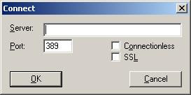
Type in the server location, this could be a dns name or ip address. Then just press OK. Next, we have to bind, click Connection then Bind.


Type in your username and password which has the permission to modify user's attribute, then press OK. Then click Browse then Modify.


  • In the DN textbox, type the DN for the user which you want to modify his/her attribute. For example, the DN for the administrator account would be something like this CN=administrator,CN=users,DC=srv1,DC=domain,DC=com.

  • In the attribute textbox, type in the name of the attribute that you want to modify. For example, if you want to modify the givenName of a user, type in givenName.

  • Type in the new value for the attribute that you want to change in the Values textbox.

  • Press enter, you can add another new attribute and value again if you want to modify more than one attribute.

  • If you're done then click Run.


To verify the attribute modification use the search operation agains AD, press Ctrl+S or click Browse then Search in LDP.


Read more...
top